| As of August 2020 the site you are on (wiki.newae.com) is deprecated, and content is now at rtfm.newae.com. |
Difference between revisions of "CW308T: Stand-Alone Simple Serial Example (AVR or XMEGA)"
(→USB Serial Usage) (Tag: VisualEditor) |
(Tag: VisualEditor) |
||
| Line 1: | Line 1: | ||
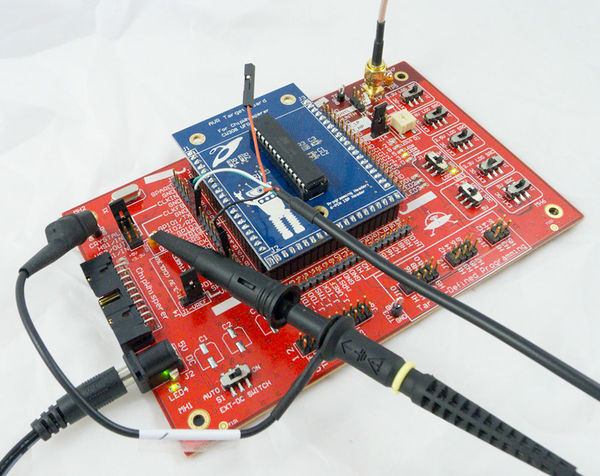
| − | + | [[File:P1090078.jpg|thumb|600x600px|Example of attaching to the AVR target device.]] | |
| − | [[File:P1090078.jpg| | + | |
== Board/Jumper Settings == | == Board/Jumper Settings == | ||
Revision as of 07:13, 24 September 2016
Contents
Board/Jumper Settings
The following specifies what various jumpers should be set to:
| Switch | Setting | Note |
|---|---|---|
| EXT-DC Switch (S1) | ON | Can be used as on/off switch. |
| 3.3V Source | LDO | Set VCC3.3 as coming from LDO. |
| 3.3V LDO Source | EXT-DC | Set LDO source as DC-Power Jack. |
| Others | Don't Care |
| Jumper | Setting | Note |
|---|---|---|
| J3 | Jumper mounted on "CRYSTAL" setting (top row of pins). | Route on-board crystal oscillator |
| J4 | Jumper mounted on right two pins (board default). | Specifies victim board sets VREF voltage. |
| J14 | Jumper mounted on left two pins (board default). | Uses FILT output from victim board. |
| X1 Crystal Socket | Note |
|---|---|
| 7.37 MHz Crystal | This is default frequency for programmed software. Can use another frequency for custom programs. |
With that setup done, you can proceed to the next section.
Mounting Target Board
The selected target board (AVR or XMEGA) should be placed onto the main victim area. See the CW308 UFO Target page for details.
Connecting Oscilloscope
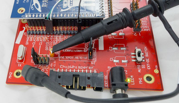
The oscilloscope needs two connections. The trigger should be connected to GPIO4 (a test point is provided for this), and the measurement should be done via the SMA J17 (marked VOUT). Note you can also use test point TP5 with a regular oscilloscope probe, but it will provide much worse performance.
The oscilloscope should be set to AC-coupled mode to eliminate the constant DC offset.
USB Serial Usage
This can either be connected at J1 (the 20-pin ChipWhisperer header), or the pin headers directly beside the victim board. The pin headers do not provide diode clamping, where as the connections at J1 have diode clamping.

