| As of August 2020 the site you are on (wiki.newae.com) is deprecated, and content is now at rtfm.newae.com. |
Difference between revisions of "CW506 Advanced Breakout Board"
From ChipWhisperer Wiki
(→Connection Routing) |
(→Schematic) |
||
| Line 21: | Line 21: | ||
== Schematic == | == Schematic == | ||
| − | The schematic is available in two formats - PDF and schematic images. | + | The schematic is available in two formats - PDF and schematic images. Click the images for full resolution. |
| − | * [[:File:NAE-CW506-02-SCH.pdf|Schematic PDF (NAE-CW506-02)]] | + | * [[:File:NAE-CW506-02-SCH.pdf|Schematic PDF (NAE-CW506-02: June 1st, 2016)]] |
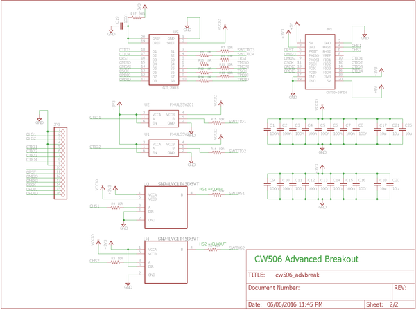
[[File:NAE-CW506-02_page1.png|600px]] | [[File:NAE-CW506-02_page1.png|600px]] | ||
[[File:NAE-CW506-02_page2.png|600px]] | [[File:NAE-CW506-02_page2.png|600px]] | ||
Revision as of 02:48, 7 June 2016
Background
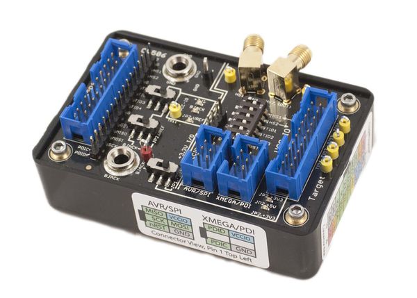
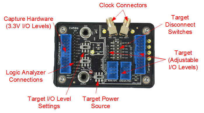
The CW506 is a simple but powerful breakout board for devices using NewAE Technology's 20-Pin Connector standard. Almost all of our target boards and capture hardware feature this connector, making the breakout board widely applicable to our product line.
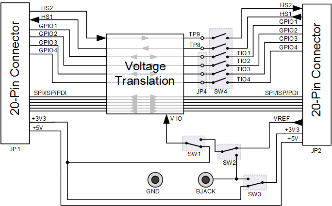
The breakout board features a variety of voltage translators, test points, connectors, and switches that makes it simple to interface various test equipment and target devices together. This includes both connecting other lab equipment, along with connecting ChipWhisperer capture hardware to your own targets.
Switch Settings
Use Cases
Schematic
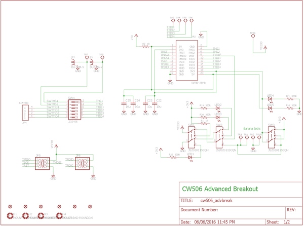
The schematic is available in two formats - PDF and schematic images. Click the images for full resolution.
