| As of August 2020 the site you are on (wiki.newae.com) is deprecated, and content is now at rtfm.newae.com. |
CW1200 HW Setup
From ChipWhisperer Wiki
Revision as of 07:37, 28 September 2018 by Adewar (Talk | contribs) (Created page with "This tutorial uses the CW1200_ChipWhisperer-Pro hardware. # Remove the ChipWhisperer-Pro main capture hardware, UFO Board, and SMA cable from the ChipWhisperer-Pro case....")
This tutorial uses the CW1200_ChipWhisperer-Pro hardware.
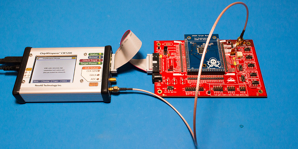
- Remove the ChipWhisperer-Pro main capture hardware, UFO Board, and SMA cable from the ChipWhisperer-Pro case.
- Attached the UFO board to the ChipWhisperer-Pro with the 20-pin cable, and connect the VOUT SMA connector to the MEASURE input.
- Power up the ChipWhisperer-Pro with the 5V DC power adapter, and connect the USB cable to the computer.
- If this the first time powering up, you will need to install the drivers (see CW1200_ChipWhisperer-Pro).
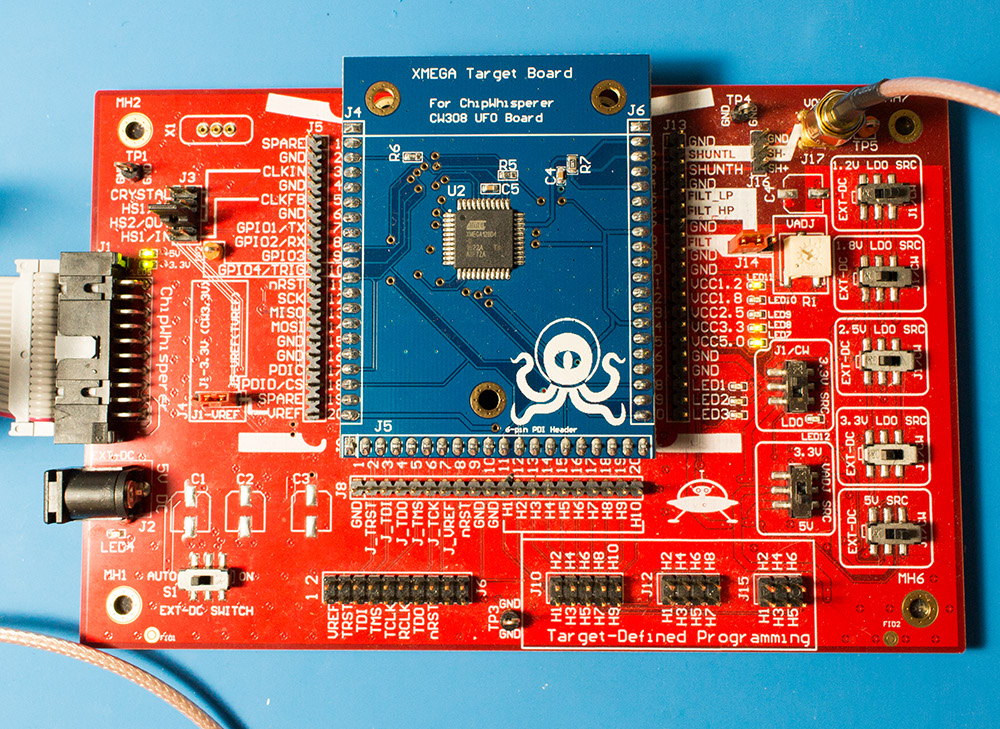
Note if you have modified the UFO board the jumpers may no longer be at default locations. The jumper settings required are:
- XMEGA Target board mounted
- J3 routes HS2/OUT to CLKIN
- J1 set to "J5-VREF" (right two pins shorted)
- J14 set to "FILT" (left two pins shorted)
- "3.3V SRC" switch set to "J1/CW"

