| As of August 2020 the site you are on (wiki.newae.com) is deprecated, and content is now at rtfm.newae.com. |
Difference between revisions of "CW304 Notduino Target"
| Line 272: | Line 272: | ||
[[File:Cw304_schematic.png|image]] | [[File:Cw304_schematic.png|image]] | ||
| + | |||
| + | {{Template:Hardware}} | ||
[[Category:Targets]] | [[Category:Targets]] | ||
Revision as of 07:11, 17 January 2017
Contents
CW304 Target: Notduino (ATMega328P Board)

The Notduino is used as a target for the ChipWhisperer Capture system. This includes interfacing to the CW-Lite (CW1173) and ChipWhisperer Capture Rev 2 (CW1002). The Notduino has the following features/specifications:
- 3.3V Operating Voltage
- Atmel ATMega328P Microcontroller
- Power analysis on VCC rail
- Power glitching using CW1173 Crowbar
- One user LED
- One user push-button
- Clock input or output line
- 6 user I/O lines (including trigger to ChipWhisperer)
- Optional crystal mounting holes
- USART Lines for communication
- Header to connect USB-Serial for Arduino bootloader usage
Board Usage
The board is connected to the standard 20-pin target connector used on the ChipWhisperer system. In addition you will require connection of the SMA connector to perform power measurements:

Like most of our targets, the Notduino can be used without the capture hardware. In this case the SMA connector is used to connect to the regular oscilloscope, and a USB-Serial is used for communications:

VCC Jumper Settings (JP2)
JP2 uses our standard 6-pin connector, similar to the Multi-Target board. On the NOTDuino board only the VCC shunt is present however, which means you cannot perform measurements on a GND shunt.
Using the header in the following position is required for both side-channel power analysis and voltage-glitching attacks:

If you are only doing clock glitching attacks (without associated power measurement), you could short the jumper:

Clock Jumper Settings (JP8/JP9)
The clock jumpers allow you to connect the HSOUT and HSIN lines to the two XTAL pins on the ATMega328P. Normally you would mount JP8, which routes the HSOUT line from the ChipWhisperer to the "External Clock Input" on the ATMega328P.
You can also try mounting a crystal at Q1 (along with require capacitors typically in 18pF-22pF range) at C8 and C9. If this is done, you will need to ensure the fuses for the ATMega328P are programmed for the "Full Output Swing", and you can then route the output of the crystal buffer to CLKIN by mounting pin C9.
Finally, you can also solder a wire from pin 14 (PB0) of the ATMega328P to pin 10 (PB7, the XTAL out pin). This allows you to enable the internal oscillator of the ATMega328P, and also enable the "Clock Out" pin. This clock output drives the internal oscillator frequency onto the output pin, which you then route to the HSIN lines.
Serial Header (JP4)
The serial header at JP4 provides a method of connecting a standard serial cable to the NOTDuino board. Note the "RST" pin is broken out, allowing you to use a serial cable with a "DTR" pin to control the reset of the ATMega328P (which is required for the Arduino bootloader).
Note you will need to mount an appropriate crystal at Q1, along with C8 and C9 if not using the ChipWhisperer for a clock source.
| Silkscreen | ATMega328P | Arduino Name | Notes |
|---|---|---|---|
| GND | Ground | ||
| 3V3 | VCC | If NOT connected to CW-Lite, can power from 3-5V | |
| TXD | PORTD.1 | Pin 1 | Output from AVR |
| RXD | PORTD.0 | Pin 0 | Input to AVR |
| RST | Reset |
User IO Header (JP3)
The user IO header breaks out
| Silkscreen | ATMega328P | Arduino Name | Notes |
|---|---|---|---|
| GND | Ground | ||
| A5 | PORTC.5 | Analog Pin A5 | |
| A4 | PORTC.4 | Analog Pin A4 | |
| A3 | PORTC.3 | Analog Pin A3 | |
| A2 | PORTC.2 | Analog Pin A2 | |
| 1 | PORTC.1 | Analog Pin A1 | |
| 0 | PORTC.0 | Analog Pin A0 | Trigger |
Using Arduino Software
If you wish to use the Arduino software with the NOTDuino board, there is two main methods of doing that:
- Using ChipWhisperer-Lite as programmer.
- Using board entirely stand-alone.
Using ChipWhisperer-Lite as Programmer
If using the board with the ChipWhisperer-Lite attached (i.e. using the ChipWhisperer-Lite as the capture hardware), this requires the fewest modifications. To use the board you will need to:
- In the tutorials, set the CLKGEN frequency to 16.00 MHz instead of 7.37 MHz.
- Use the integrated AVR programmer, program the compiled
.hexfile. This file can be found in two ways:- For Arduino 1.6.5 or later, there is an Export Compiled Binary from the Sketch menu.
- For earlier version of Arduino, enable the Show vervose output during compilation in the Preferences menu. This will show you where the
.hexfile is located (NOTE: it changes after every compilation).
Using Board Entirely Stand-Alone
If using the board stand-alone, you will need to perform the following:
Program the Arduino bootloader into the ATMega328P. This can be done with the ChipWhisperer-Lite programmer, or with a standard programmer and the 6-pin ISP header at JP6.
Also program default fuses for the Arduino to select the external crystal.
- Mount a 16 MHz crystal at Q1, and appropriate capacitors at C8 and C9 (typically in range of 18-22pF depending on the crystal). Remove jumpers JP8 and JP9.
- Connect a USB-Serial adapter to JP4. You can connect the VCC line of a serial port to the "+3v3" line, as the board can be powered from 5V when not connected to the ChipWhisperer-Lite. Never connect the board to a 5V line with the ChipWhisperer-Lite attached, as it will destroy the ChipWhisperer-Lite.
Kit Assembly
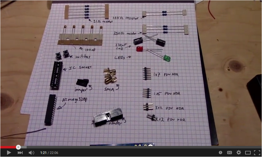
The Notduino kit includes all the parts to assemble the Notduino kit. The following shows the kit parts:

Kit Parts
Which you can break out into the following parts:

The following lists all the parts in the kit:
| Qty | Description |
|---|---|
| 1 | NPCB-CWTARG-NOTDUINO-02 |
| 5 | 100nF Ceramic Capacitor (Marked with '104') |
| 2 | 220uF Electrolytic Capacitor |
| 5 | 51-ohm 1/4W Resistor (Green Brown Black Gold Brown), 1 spare |
| 3 | 330-ohm 1/4W Resistor (Orange Orange Black Black Brown), 1 spare |
| 2 | 10k-ohm 1/4W Resistor (Brown Black Black Red Brown), 1 spare |
| 1 | Red 5MM LED |
| 1 | Green 5MM LED |
| 1 | ATMega328P-PU |
| 1 | 28-pin IC Socket |
| 2 | Tactile Pushbuttons |
| 2 | Jumpers |
| 1 | 1x5 Pin Header |
| 1 | 1x7 Pin Header |
| 1 | 2x3 Pin Header |
| 1 | 2x4 Pin Header |
| 1 | 20-Pin Shrouded Header |
| 2 | SMA Edge-Mount Connector |
Note the resistors use a 5-band colour code, which is different from the "regular" colour code you might be used to. The following shows the resistors, note the colour code listed in the parts list above. Each of the resistors have an extra provided, so when you assemble the board you should have three left-over resistors.

Assembly Process
There is no specific assembly procedure for the board. The values of components have been marked on the blank PCB, here are some general instructions for the assembly process:
- You can use lead or lead-free solder due to the immersion gold finish of the PCB.
- Mount parts starting with the lowest height (such as resistors and ceramic capacitors) first.
- Note there is an extra of each of the resistors - i.e. you only need one 10k resistor (R4) but are provided two.
- Watch the polarity of LED1 and LED2. The flat edge of the LED should match the flat marking on the silkscreen.
- The electrolytic capacitors (C7 and C6) have the negative marked on them. Be sure to match up the negative with the "-" marking on the PCB. The two capacitors have the negative terminal facing each other.
- The shrouded header has an orientation - match up the notch in the 20-pin header with the mark on the PCB silkscreen.
- See the picture at the beginning of this section for details of the assembly.
- The test-points (including the "GND") can be made using a cut-off resistor lead. This gives you something to clip a test point onto.
Schematic
