| As of August 2020 the site you are on (wiki.newae.com) is deprecated, and content is now at rtfm.newae.com. |
Completing Tutorial with CW1002 (ChipWhisperer Capture Rev2)
Contents
Completing Tutorial with CW1002 (ChipWhisperer Capture Rev2)
Note the following is only applicable to the use of the ChipWhisperer-Capture Rev 2 hardware (aka the CW1002). See #Completing_Tutorial_with_CW1173/CW1200 if you are not using this hardware.
Setting up the Hardware
This tutorial uses the CW1002_ChipWhisperer_Capture_Rev2 hardware along with the CW301_Multi-Target board. This hardware is the standard setup for all basic tutorials.
This example uses the Atmel AVR in 28-pin DIP programmed with a simpleserial communications protocol. This is the default firmware programmed into the devices, so you shouldn't need to do anything. If you've erased the device, you can see programming instructions in the Installing_ChipWhisperer section.
The Multi-Target board should be plugged into the ChipWhisperer Capture Rev2 via the 20-pin target cable. The VOUT SMA connector is wired to the LNA input on the ChipWhisperer-Capture Rev2 front panel. The general hardware setup is as follows:
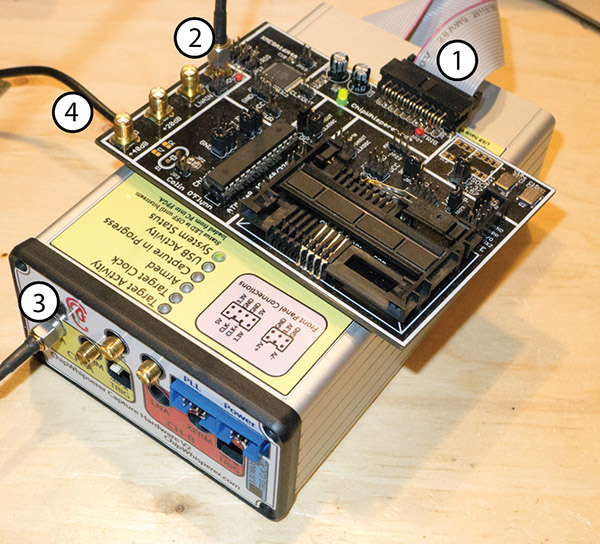
- 20-Pin Header connects Multi-Target to Capture Hardware
- VOUT Connects to SMA Cable
- SMA Cable connects to 'LNA' on CHA input
- USB-Mini connects to side (NB: Confirm jumper settings in next section first)

Jumpers on the Multi-Target Victim board are as follows:
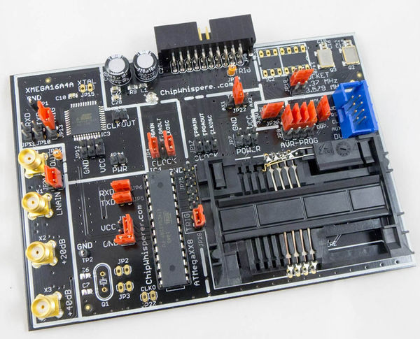
- NO jumpers mounted in XMEGA Portion or SmartCard Portion (JP10-JP15, JP19, JP7-JP8, JP17)
- 3.3V IO Level (JP20 set to INT.)
- The 7.37 MHz oscillator is selected as the CLKOSC source (JP18)
- The CLKOSC is connected to the AVR CLock Network, along with connected to the FPGAIN pin (JP4)
- The TXD & RXD jumpers are set (JP5, JP6)
- Power measurement taken from VCC shunt (JP1)
- The TRIG jumper is set (JP28) (NOTE: Early revisions of the multi-target board do not have the TRIG jumper and you can ingore this).
For more information on these jumper settings see CW301_Multi-Target .

Setting up the Software
It is assumed that you've already followed the guide in Installing_ChipWhisperer. Thus it is assumed you are able to communicate with the ChipWhisperer Capture Rev2 hardware (or whatever capture hardware you are using). Note in particular you must have configured the FPGA bitstream in the ChipWhisperer-Capture software, all part of the description in the installing guide.
Assuming this setup is complete, you can confirm you are able to communicate with the hardware by running the example capture of traces given in the Tutorial_B5_Breaking_AES_(Straightforward).
Programming the Example
- We assume the hardware is already connected as at the beginning of this tutorial. If not go back & confirm this hardware setup.
- Next, you will need to program the AVR itself. On Windows we will make use of the free Atmel Studio 4.19. You can find a direct link here: Direct Link to Atmel Studio 4.19 Binary which will require you to enter an email address to receive the download link. Note it is possible to use
avrdude, a command-line program which is part of WinAVR instead if you wish. However since many people find the graphical interface of AVRStudio easier, this guide will use AVRStudio. Be sure to install the USB drivers as part of the package. - Plug in the USB-A Connector on the rear side of the ChipWhisperer Rev2. This should trigger the driver installation, which will detect the device as a AVR-ISP MK2. You can leave the USB-Mini cable plugged in during this operation, or unplug the USB-Mini cable from the ChipWhisperer & plug in the USB-A cable.
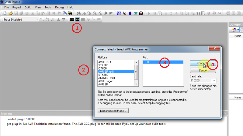
Once AVR Studio is installed, open the main window. From the toolbar select either the Con or AVR icon, and select the AVR-ISP MK-II Device:
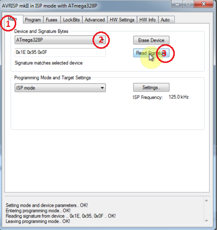
In the window that opens, select the Main tab. Select the device type as AtMega328P, and hit Read Signature. You should get an indication that the device signature was successfully read!
Finally we can program the chip. To do so switch to the Program tab, select the
simpleserial_nocrypto.hexfile that was generated in Step 4, and hit Program. If it's successful you should see some output data saying so.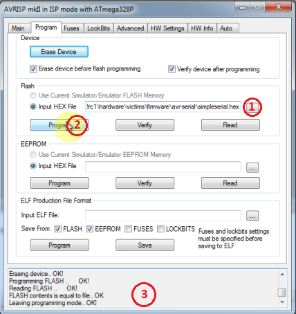


warningBe sure to select the correct .hex file! Otherwise the system won't work & it can be frusturating to troubleshoot. It's a good idea to look at the 'last modified' date which shows up when you go to select the file. Check that it roughly corresponds to when you compiled the file.
That's it! You've now built a custom application & programmed it into the AVR. We haven't yet verified it's working, which is the next step.
Communicating from CW-Capture Software
Next, open the CW-Capture software. Then perform the following steps:

- Switch to the General Settings tab
- As the Scope Module, select the ChipWhisperer/OpenADC option
- As the Target Module, select the Simple Serial option
Next, you'll have to configure the target module:

- Switch to the Target Settings tab
- As the connection, select the ChipWhisperer option
Now, download the FPGA Firmware:

- Optional: Run the Download CW Firmware tool. You should have configured this already before. Note that from release 0.09 of ChipWhisperer the FPGA is automatically programmed when you attempt to connect, so you can skip this step if using a recent release (i.e. any release in 2015 or later).
- If you switch to the Debug Logging output, you should see an indication the FPGA was programmed. If you were already using the device, it will skip the download. Normally you can skip steps 6 & 7 if you've already performed the FPGA download once since powering on the device. Note that

- Press the button labeled Master: DIS, where DIS has a circle around it. If it works, it will switch to green and say CON.

- Switch to the General Settings tab.
- Hit the Open Monitor button.
- Resize the monitor window. The monitor will show sent & received data to the target.
- Hit the Run 1 button. You may have to hit it a few times, as the very first serial data is often lost. You should see data populate in the Text Out field of the monitor window. Note that each byte of the Text In is incremented in the Text Out field.