| As of August 2020 the site you are on (wiki.newae.com) is deprecated, and content is now at rtfm.newae.com. |
Difference between revisions of "Setting up Software for B1"
| Line 11: | Line 11: | ||
Next, open the CW-Capture software. Then perform the following steps: | Next, open the CW-Capture software. Then perform the following steps: | ||
| − | [[File: | + | [[File:cwsetup_scriptselection.png|600px]] |
| − | # Switch to the '' | + | # Switch to the ''Python Console'' tab. |
| − | # | + | # The script selection window (2) lists available example scripts. Scroll down to "connect_cwlite_simpleserial.py" and click on it. |
| − | # | + | # You will see the script contents appear in the "Script Preview" window (3). You can either hit the "Run" button or double-click the filename of the script to execute it. Do either of those now. |
| − | + | The window should change to indicate the connect succeeded: | |
| − | [[File: | + | [[File:cwsetup_scriptselection_cwliterun.png|400px]] |
<ol start="4" style="list-style-type: decimal;"> | <ol start="4" style="list-style-type: decimal;"> | ||
| − | <li> | + | <li>The console lists the exact script that is executed. Note you could have manually executed the script commands line-by-line in this console.</li> |
| − | <li> | + | <li>The "Scope" and "Target" buttons will show as connected.</li> |
| + | <li>The Status Bar will show a connection.</li> | ||
| + | </ol> | ||
| − | + | Note in previous software versions, this tutorial took you through manual setup. This can still be done (using the GUI), but instead now the API has been made more powerful, so the example configuration script will be used instead. | |
| − | [[File: | + | To do so, simply scroll down and select the "setup_cwlite_xmega_aes.py" file: |
| + | [[File:cwsetup_scriptselection_xmegaconfig_cwliterun.png|400px]] | ||
| − | + | You'll nice the contents of the script contain the following setup: | |
| − | + | ||
| − | + | ||
| − | + | TODO SCRIPT | |
| − | <ol start=" | + | <ol start="14" style="list-style-type: decimal;"> |
| − | + | ||
| − | + | ||
| − | + | ||
| − | + | ||
| − | + | ||
| − | + | ||
| − | + | ||
| − | + | ||
| − | + | ||
| − | + | ||
| − | + | ||
| − | + | ||
| − | + | ||
| − | + | ||
| − | + | ||
| − | + | ||
| − | + | ||
| − | + | ||
| − | + | ||
| − | + | ||
| − | + | ||
| − | + | ||
| − | + | ||
| − | + | ||
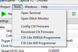
<li><p>You can now program the XMEGA device! To do so, open the XMEGA Programmer from the ''Tools'' menu:</p> | <li><p>You can now program the XMEGA device! To do so, open the XMEGA Programmer from the ''Tools'' menu:</p> | ||
<p>[[File:cw1173_xmegaproga.png|image]]</p></li> | <p>[[File:cw1173_xmegaproga.png|image]]</p></li> | ||
Revision as of 14:05, 17 September 2017
It is assumed that you've already followed the guide in Installing_ChipWhisperer. Thus it is assumed you are able to communicate with the ChipWhisperer CW1173 hardware (or whatever capture hardware you are using). Note in particular you must have configured the FPGA bitstream in the ChipWhisperer-Capture software, all part of the description in the Installing_ChipWhisperer guide.
Assuming this setup is complete, you can confirm you are able to communicate with the hardware by running the example capture of traces given in the CW1173_ChipWhisperer-Lite quick-start.
Programming the Example
Note with the CW1173 you need to configure a clock before programming of the device will succeed. Programming of the target device will be done as part of the CW-Capture software setup, discussed next.
Communicating from CW-Capture Software
Next, open the CW-Capture software. Then perform the following steps:

- Switch to the Python Console tab.
- The script selection window (2) lists available example scripts. Scroll down to "connect_cwlite_simpleserial.py" and click on it.
- You will see the script contents appear in the "Script Preview" window (3). You can either hit the "Run" button or double-click the filename of the script to execute it. Do either of those now.
The window should change to indicate the connect succeeded:

- The console lists the exact script that is executed. Note you could have manually executed the script commands line-by-line in this console.
- The "Scope" and "Target" buttons will show as connected.
- The Status Bar will show a connection.
Note in previous software versions, this tutorial took you through manual setup. This can still be done (using the GUI), but instead now the API has been made more powerful, so the example configuration script will be used instead.
To do so, simply scroll down and select the "setup_cwlite_xmega_aes.py" file:

You'll nice the contents of the script contain the following setup:
TODO SCRIPT
You can now program the XMEGA device! To do so, open the XMEGA Programmer from the Tools menu:
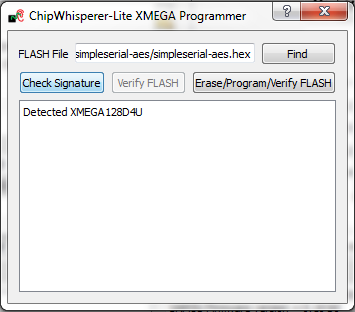
Hit the Check Signature button and confirm the device is detected. If not you may have issues with the clock setup.
Using the Find button, navigate to the
simpleserial-base.hexwhich you built earlier with themakecommand. You can then press the Erase/Program/Verify button, and confirm the file is programmed into the XMEGA device: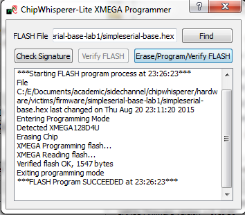
Note the programmer dialog not only shows the successful programming status, but also shows when the
.hexfile was last modified. Always confirm this matches with when you last remember compiling the program -- if it is widely different this suggests you have selected the wrong file!Finally we can check communications with the programmed file:


- Close the XMEGA programmer dialog.
- Open the status monitor under Tools > Encryption Status Monitor.
- Resize the monitor window. The monitor will show sent & received data to the target.
- Hit the Run 1 button (
 ). You may have to hit it a few times, as the very first serial data is often lost. You should see data populate in the Text Out field of the monitor window. Note that each byte of the Text In is incremented in the Text Out field.