| As of August 2020 the site you are on (wiki.newae.com) is deprecated, and content is now at rtfm.newae.com. |
Tutorial A3 VCC Glitch Attacks
For the older V3.x tools, see V3:Tutorial A3 VCC Glitch Attacks
This advanced tutorial will demonstrate power glitch attacks using the ChipWhisperer system.
Contents
Background on VCC (Power) Glitching
The previous clock glitching tutorials looked into the assumption of a constant clock. But instead we can modify the voltage of the device, causing for example a failure to correctly read a memory location or otherwise cause havoc with the proper functioning.


Background on Glitch Generation
For more details, please see Tutorial_A2_Introduction_to_Glitch_Attacks_(including_Glitch_Explorer), this tutorials assumes you have already performed the clock glitching tutorial. This tutorial will use the Glitch Explorer, which is described in the previous tutorial.
The glitch generation hardware is the same as used in the clock glitching attack. The generated glitches are synchronous to the device clock, and inserted at a precise offset from the clock edge.
Glitches can be inserted continuously or triggered by some event. The following figure shows the generation of two glitches:

The VCC glitching method here uses an electronic switch (a MOSFET) to short the power line to GND at specific instances. The following figure shows the basic function of this system:

This method allows use with the standard side-channel analysis development board, which has resistors inserted into the VCC lines already. The downside of this method is that it can only generate short glitches, since the power consumption through the shunt resistor will short out the resistor.
The MOSFET glitching hardware is built into the ChipWhisperer-Lite (both CW1173 and CW1180) board. The ChipWhisperer-Capture Rev2 uses an external VCC glitching board.
Hardware Setup
ChipWhisperer-Lite (CW1173) with built-in XMEGA Target
The XMEGA target will work out-of-the-box for this tutorial. As usual, no hardware setup is required - everything on the CW-Lite board is ready to go.
ChipWhisperer-Lite (CW1173/CW1180) with external AVR (NOTDUino/Multi-Target)
The AVR is an extremely reliable target to glitch. To do this, you need to connect the following cables:
- SMA Cable from the Glitch port to the VCC shunt.
- 20-Pin Target Cable for Clock & Data.
- Optional: SMA Cable from the Measure port to the VCC shunt (can be used to monitor glitch insertion).
The following shows an example of connecting the NOTDuino target to the ChipWhisperer-Lite:

If using a target with only a single SMA, only connect the Glitch port. The measure port is optional to allow you to monitor the VCC line as you are inserting the glitch.
Setting up Glitch Example
Firmware Setup
Just as in the clock glitching example, you will be required to program the AVR microcontroller with an example you can glitch. Once again program in the glitch example code to use the glitch1() function, as described in Tutorial_A2_Introduction_to_Glitch_Attacks_(including_Glitch_Explorer).
If using the AVR target, be sure to modify the makefile to select the new target type (i.e. if you previously targeted the XMEGA, that hex-file will not work on the NOTDuino).
Programming the device is also described in Step #4 in the following section.
Software Setup
-
Select the
connect_simpleserial.pyscript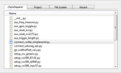
-
Run the
connect_simpleserial.pyscript, by pressing the Run button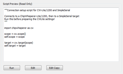
-
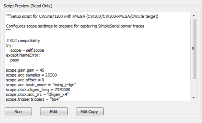
Setup up the settings by running the appropriate setup script for your device
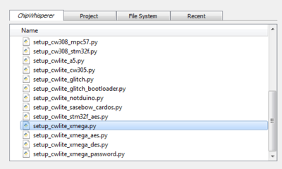
-
Run the setup script by pressing the run button, if you want to see what parameters the script changes, inspect the preview
-
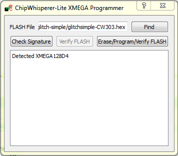
Open the appropriate programmer from top main menu Tools, and in the dialog press Check Signature to verify you can connect to the target
-
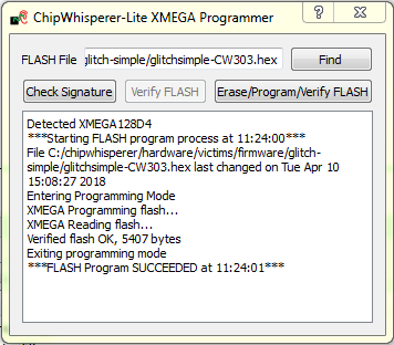
Find the correct firmware file, previously compiled for the target you are using, and press the Erase/Program/Verify FLASH
-
Time to setup the voltage glitching parameters. Start with the Glitch Module section under the Scope Settings tab
- For the ChipWhisperer-Lite (CW1173/CW1180), set Target HS IO-Out option to CLKGEN.
-
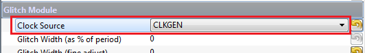
Set the Clock Source as CLKGEN:
Setup the CLKGEN Module to Generate a 7.37 MHz clock and route it through the Glitch Generator
- Switch the Freq Counter Src to the CLKGEN Output
- Set the Desired Frequency to 7.37 MHz. Note you should only adjust the 'frequency' portion of this, if you highlight the entire field you may not be able to type the frequency into the system.
- Confirm the DCM Locked checkbox is checked, if not hit the Reset CLKGEN DCM box. Check the Freq Counter to ensure the system is correctly generating about a 7.37 MHz clock.
Under the Glitch Module set the Clock Source as CLKGEN:
Set the Target HS IO-Out appropriately. This depends on the hardware in use:
- For the ChipWhisperer-Lite (CW1173/CW1180), set Target HS IO-Out option to CLKGEN.
Connect the Serial Port
- For the XMEGA Target (including the CW-Lite integrated target), perform the following:
- Switch to the Scope Settings tab, and scroll down to Target IOn Pins
- Switch the Target IO1 to be Serial RXD
- Switch the Target IO2 to be Serial TXD
From the Tools menu select Open Terminal, and press Connect on the terminal:
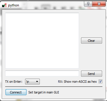
- The baud rate for this system is 38400, which should be the default for the ChipWhisperer serial port.
- For the XMEGA Target (including the CW-Lite integrated target), perform the following:
Program the
.hexfile into the target. When programming the AVR, it needs a working clock source before the programming will succeed. Now that this is enabled, you can use the appropriate programmer (such as the AVR or XMEGA programming from the Tools menu if using a CW-Lite) to program the hex file.You should see the "Hello" message printed on the terminal emulator window.
warning
Releases of the ChipWhisperer-Capture software prior to 0.13 had a bug in the AVR reset logic, which never released the device from reset. You must update your ChipWhisperer-Capture release in order to complete this tutorial.
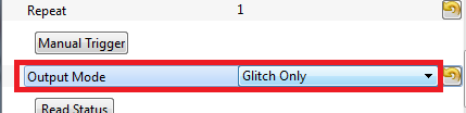
Setup the Glitch Module to NOT output anything by default VERY IMPORTANT TO AVOID DAMAGE
Under the Glitch Module set the Output Mode as Glitch Only, this is the step that insurances you do not cause constant glitches:
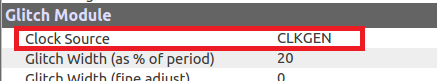
For the ChipWhisperer-Lite (CW1173 or CW1180):
Under the Glitch Module set the Clock Source as CLKGEN
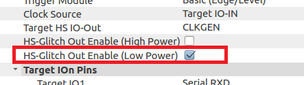
Check the box marked HS-Glitch Out Enable (Low Power):
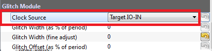
For the ChipWhisperer-Capture Rev 2 (CW1002):
Under the Glitch Module set the Clock Source as TargetIO-IN:
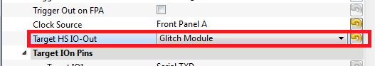
Under the Target HS IO-Out option select the Glitch Module, ensuring you've already set the Output Mode as Glitch Only under Glitch Module:
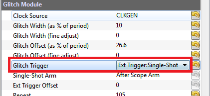
Switch the Glitch Trigger mode to Ext Trigger:Single-Shot:
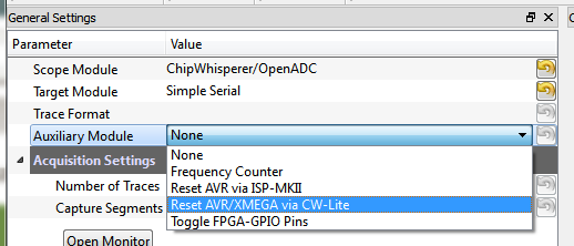
Switch to the General Settings tab, and select the appropriate "Auxiliary Module":
- For ChipWhisperer-Lite (CW1173/CW1180), select "Reset AVR/XMEGA via CW-Lite"
- For ChipWhisperer-Capture Rev 2, select "Reset AVR via ISP-MKII"
- Switch to the Aux Settings tab. Depending on your module you will see different settings here, for example the ChipWhisperer-Lite lets you select between AVR and XMEGA targets. This normally defaults to the "XMEGA" device, so be sure to switch this to the "AVR" device if using the NOTDuino or Multi-Target boards!
Press the Test Reset button in the Aux Settings tab. This should reset the AVR target. Confirm this by monitoring the terminal emulator window, and check the startup message (of "hello") is printed again.
You can also use the "Reset" button on the NOTDuino to confirm the startup message is printed.
- Switch to the Target Settings tab, and remove all the text in the Load Key Command, Go Command, and Output Format fields.
Optionally, you can also configure the power measurement setup too:
Monitoring Glitch Insertion
We can optionally enable the power analysis capture, and monitor how the power consumption changes as we insert a glitch. To do this:
- Switch to the Scope Settings tab.
- Switch the ADC Clock Source as being CLKGEN x4.
- Press Reset ADC DCM, confirm the frequency is 29.5 MHz as expected.
- Switch the Trigger Setup --> Mode to be Rising Edge
- Switch the Trigger Setup --> Total Samples to be 1000
- Switch the Gain Setting --> Setting to be 40. You might need to adjust this for different hardware.
Press Capture 1, confirm some waveform is displayed. For example with the NOTDuino Target on the ChipWhisperer-Lite, the waveform looks like this:
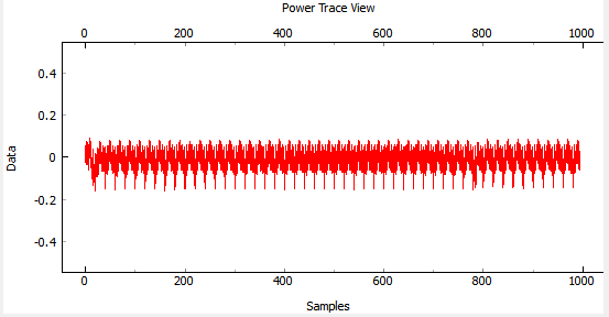
- If this does't work: check the trigger in use is the Target IO4 pin.
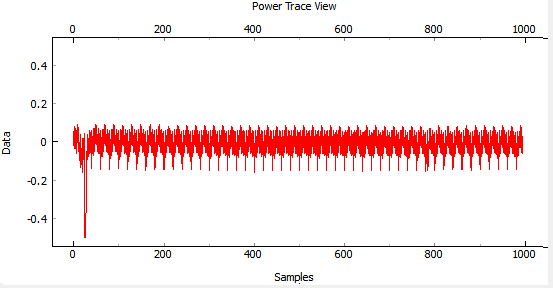
Play around a bit with the glitch width, offset, and repeat. You should see different effects in the power consumption traces. For example the following shows a narrow (15% pulse width) glitch being inserted:
Starting the Glitch Attack
We'll now look at glitching this routine. As before after sending the
Athe system goes into an infinite loop, and sends1234after exiting from the loop. Using VCC glitching we'll escape from this loop!Rather than using the manual trigger, we'll jump right into using the Glitch Explorer to break this target. First, we'll setup some basic glitch parameters for your specific target.
- Switch to the Target Settings tab, and set the Output Format to
$GLITCH$. Open the Glitch Explorer, and hit Capture 1 a few times. Confirm this populates the table with various examples.
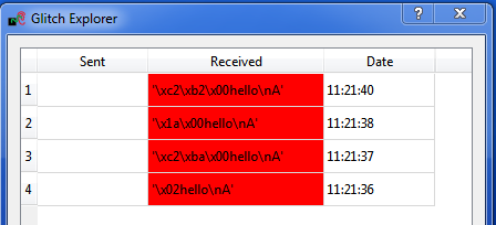
We need to setup the Normal Response and Successful Response. Note in this example the normal response has a little random noise we want to ignore, but we want to capture when the device resets after the glitch and sends the "hello" message twice. We could accomplish this with the following bit of Python code:
s.endswith("hello\nA") and (len(s) < 12)This looks for both the ending without glitch, and the length of the string isn't too long. In the case of the successful glitch, we just want to see if "1234" is printed. This can be accomplished in Python with:
"1234" in s
You can always experiment using the Python Console to see how your potential systems work. For example here is checking that the first line works:
>>> s = "\x1ahello\nA"
>>> s.endswith("hello\nA") and (len(s) < 12)
True
>>> s = "\x1ahello\nAhello\nA"
>>> s.endswith("hello\nA") and (len(s) < 12)
False
Finally, configure the Glitch Explorer:
- Set the Normal Response to
s.endswith("hello\nA") and (len(s) < 12) - Set the Successful Response to
"1234" in s
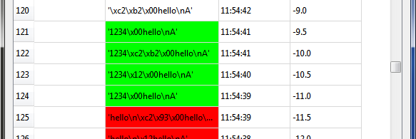
You can test the updated color-coding seems to be working too with a few Capture 1 events.
- Set the Normal Response to
Using the following table, set the Glitch Width (as % of period) and Repeat on the Scope Settings tab:
Parameter AVR on Multi-Target or NOTDuino Glitch Width (as % of period) 49 Repeat 10 - Finally, let's configure the Glitch Explorer to give us the required sweep of the Offset parameter.
- Adjust the Glitch Offset (as % of period) up or down by 1 in the Glitch Module settings. We do this only to get the required string printed to the Script Commands output.
- Set the Tuning Parameters to 1 in the Glitch Explorer.
Set the parameters as appropriate:
Option Value Name Offset Script Command ['Glitch Module', 'Glitch Offset (as % of period)'] Data Format Float Range -49 : 49 Value -49 Step 0.5 Repeat 1
On the General Settings tab:
- Ensure the Trace Format is set to None (i.e., no traces will be written to disk).
- Set the Number of Traces to 200.
- Press the Capture Multi button. You will get a warning as there is no trace writer, but can just hit Continue Anyway, since we do not want to store traces to disk.
Hopefully you will determine some useful parameters for glitching this target:
- Try reducing the Repeat parameter in the Glitch Module settings. See how few cycles you can glitch while still achieving a reliable glitch.
Once you have the glitch parameter determined, you can work on trying to recreate some of the previous tutorials such as glitching passed the password prompt.
Glitching More Advanced Targets: Raspberry Pi
It is also possible to glitch more advanced targets, such as the Raspberry Pi development board! This requires some additional hardware setup which will be discussed here.
The Raspberry Pi is a small ARM-based computer that runs Linux. This tutorial will show you how to influence a program running in userland via voltage glitching.
We will use the ChipWhisperer-Lite board, as it has integrated high-power glitching MOSFET.
Hardware Setup
warning
This tutorial can cause permanent damage to your Raspberry Pi board. The generation of glitches means driving the power supply and device beyond limits specified in the absolute maximum ratings. Only perform this tutorial if you are not too attached to your Raspberry Pi board.
YOU PERFORM THIS TUTORIAL AT YOUR OWN RISK. NEWAE TECHNOLOGY INC. IS NOT RESPONSIBLE FOR DAMAGE CAUSED BY FOLLOWING THIS TUTORIAL.
To glitch the board, you must solder a wire onto the VDD_CORE power supply, ideally as close to the BGA power pin as possible. To do this identify the power plane by looking at the schematic:
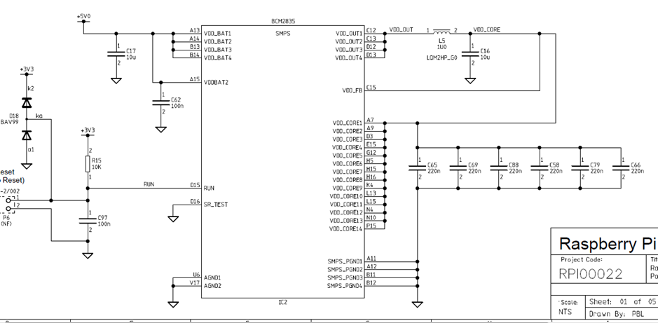
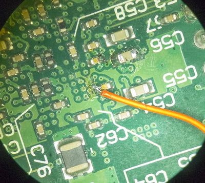
And then solder a wire onto the VCC side of a decoupling capacitor, such as C65. Check the polarity with a DMM to ensure you have the positive side and solder a fine wire to it.
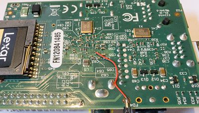
We will now mount a connector so we can connect this to the ChipWhisperer-Lite Glitch port. This will require you to check your specific revision - on this board an empty hole (test point) labeled "TP2" connects to ground, and made a handy location to connect the SMA connector to ground.
The following shows an example of soldering the SMA connector onto the board, note the GND is soldered on both top and bottom to give additional strength:
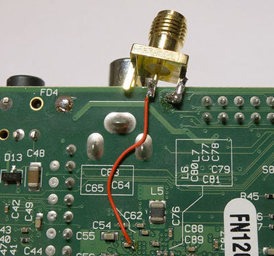
The positive side of the capacitor connects to the inner conductor of the SMA "GLITCH" port, and connect the outer connector to ground on the Raspberry Pi. At this point do not yet plug into the GLITCH port, we will do that once setup is complete.
Finally you need to boot the Raspberry Pi and connect to it. This is suggested to be done with a SSH shell over the Ethernet connection, as the Ethernet connection typically has very good protection against voltage transients. If you connect the Raspberry Pi to a monitor over HDMI, there is a chance the glitches may cause invalid voltage levels on the HDMI port which could damage your monitor.
Once you have connected to it, simply make a file called
glitch.cwith the following contents:#include <stdio.h> int main(void){ int i,j,k,cnt; k = 0; while(1){ cnt = 0; for(i=0; i<5000; i++){ for(j=0; j<5000; j++){ cnt++; } } printf("%d %d %d %d\n", cnt, i, j,k++); } }Compile to an executable with:
$ gcc glitch.c -o glitch
And run the executable:
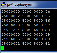
$ ./glitch
25000000 5000 5000 0
25000000 5000 5000 1
25000000 5000 5000 2
25000000 5000 5000 3
25000000 5000 5000 4
25000000 5000 5000 5
The output is split into two parts. The first three are used to monitor the glitch insertion (this is the
25000000 5000 5000, the second makes it easier for you to confirm if the Raspberry Pi has crashed.Now that you have a working system - let's break it!
Glitch Parameters
Glitching the Raspberry Pi is very simple. We just need to generate an appropriately sized glitch, as the following shows:
- Start ChipWhisperer-Capture.
- Set the Scope Module to ChipWhisperer/OpenADC, and the connection to ChipWhisperer-Lite.
- Hit the Scope Connect button. There is no target for this example.
- Set the CLKGEN frequency to 120 MHz.
- Set the Glitch module Source to CLKGEN.
- Set the Glitch Mode to Enable Only.
- Ensure the Glitch Trigger is Manual.
- Set the Repeat to 38.
- Click the HS-Glitch Out Enable (High Power) check-box.
- Connect the SMA cable for the glitch output to the Raspberry Pi.
With the output of the glitch program running, hit the Manual Trigger button. This will cause a glitch to be inserted, and observe the output of your glitch program.
Most likely the glitch width was insufficient for a glitch to be inserted, so increase the Repeat count to increase the width, and try pressing the Manual Trigger button again. In this example a glitch was successfully inserted with a width of 52, so you might want to try a few larger numbers. If you do things wrong your Raspberry Pi will crash and you'll need to reboot it and continue experimenting.
The following shows an example of inserting several glitches successfully: