| As of August 2020 the site you are on (wiki.newae.com) is deprecated, and content is now at rtfm.newae.com. |
CW1200 ChipWhisperer-Pro/Trigger Module
Unlike the ChipWhisperer-Lite, the Pro has three different trigger modes to help capture traces when it's difficult to get a concrete trigger signal. A block diagram of the trigger module is:

The first two trigger modes use a combination of the trigger inputs - the four GPIO inputs and the auxiliary SMA input. In the Capture software, these five inputs can be enabled independently and combined in three methods (AND, OR, and NAND). This combined trigger signal is the input for the edge/level and I/O decode detectors. The last trigger mode looks directly at the power trace and does not use these trigger inputs.
Edge/Level
The edge/level detector can trigger on four different events:
- Trigger input is low (0)
- Trigger input is high (1)
- Trigger input had a rising edge (0 -> 1)
- Trigger input had a falling edge (1 -> 0)
This mode is suitable when the target is using one of the GPIO pins as a trigger signal - if you have control over the target's source code, let it output a rising edge when the encryption or other operation begins.
I/O Decoder
The I/O decoder examines the trigger signal, assumes that it is either UART or SPI traffic, and outputs a trigger signal when it detects a certain pattern on the line. In the capture software, the settings for this decoder are:

- Decode Type: Which type of traffic is being captured in the trigger signal? Might be USART or SPI data.
- Trigger Data: Which data are we searching for? This setting should be a list of bytes to be detected in order. For example,
['r', '0']would detect the string "r0", and[0x07]would detect a bell character. - Baud: What baud rate does this line use? This needs to be set manually.
When using this trigger mode, target IO1/IO2 are probably the best inputs to use: these are normally the serial TX and RX lines. It's possible to enable either one of these to trigger on sending or receiving data, respectively.
Sum of Absolute Differences (SAD)
Some targets don't have nice trigger signals to detect. Sad!
The Sum of Absolute Differences module has two 128 sample buffers. The FPGA stores the ADC's 128 most recent samples in one buffer and a fixed pattern in the other. Then, after every sample, it calculates
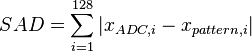
If this sum is below a fixed threshold, the output trigger signal will be set. This trigger module allows the ChipWhisperer to detect a specific pattern (for instance, an encryption operation) in a power trace without any other data.
The settings for the SAD module are:

- Point Range: The samples in the current trace to be used for the SAD module's fixed values. This range is forced to have a width of 128.
- Set SAD Reference from Current Trace: Sets the fixed 128 samples to the current selection.
- SAD Reference vs. Cursor: Shows the current output of the SAD calculation. Useful for setting the threshold - it's easy to capture a number of traces and check what typical values are for this SAD output.
- SAD Threshold: The trigger point for the SAD module. A value of 0 indicates a perfect match. If this threshold is too low, noise will stop the trigger from appearing; if it's too high, the scope will trigger at random offsets.
Note that this SAD module does not play well with downsampling: the inputs to the SAD buffer are not downsampled. This means that downsampled traces cannot be used as a reference. If you want to use this trigger type, set up your SAD trigger with downsampling turned off first.