Tutorial A1 Synchronization to Communication Lines
One of the first requirements of attacking real devices will be to synchronize to communications from the device itself.
Using ChipWhisperer-Lite Hardware
The ChipWhisperer-Lite does not currently have hardware triggers for I2C/SPI/UART. This is something which may be added in a future firmware release.
Instead, you can use the #Using External Hardware Tools method.
Using ChipWhisperer-Capture Rev2 Hardware
The ChipWhisperer-Capture Rev2 includes an arbitrary digital pattern trigger. The ChipWhisperer-Capture software provides an example of using this with a UART data line, to trigger on specific UART data.
The following is based on the Tutorial A2 Introduction to Glitch Attacks (including Glitch Explorer) tutorial, where you want to call a glitch when the glitch1() routine happens. You can use this method to trigger both glitches or side-channel power analysis measurements.
We'll use an automatic digital pattern trigger, instead of the Trigger line. This will detect when the DUT sends the A character indicating the infinite loop is going to happen.
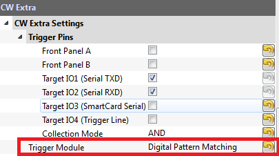
Switch the Trigger Module to Digital Pattern Matching:
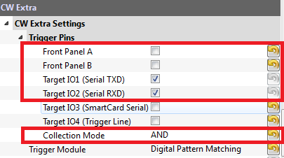
Setup the system to monitor both TX & RX lines, using an AND logic. The lines normally idle high, thus the AND combination allows you to trigger on either sent or received data:
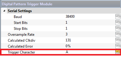
Under the Digital Pattern Trigger Module, set the Baud rate to 38400. Set the Trigger Character to
A:
When the glitch sends an A, the glitch will trigger. If you want to check the trigger is occurring, you can use the normal analog capture. To do so follow these steps:
Set the gain setting to 30:
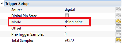
Set the trigger mode to rising edge:
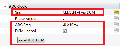
Set the ADC clock source to CLKGEN x4 via DCM, and ensure the DCM Locked checkbox indicates the DCM is locked, along with the ADC frequency being 29.5 MHz. Hit the Reset ADC DCM button if this is not the case:
Finally - we can check both the triggering and the glitches. To check the triggers our occurring:
Hit the Capture 1 box. If you have configured the automatic reset, it should send an
Acausing the trigger to occur. If the system is working the ADC will capture data, If the trigger is NOT working you will instead see a message printed about Timeout in OpenADC capture(), trigger FORCED in the Debug Logging tab:- The glitch trigger will occur whenever the trigger conditions are met now.
Using External Hardware Tools
The triggers built into the ChipWhisperer hardware are considerably more basic than those available in normal bench test equipment. This means one of the best methods to achieve advanced triggering is by using standard bench hardware. Examples of suitable hardware are:
- Teledyne Lecroy Logic Studio, a $900 logic analyzer with hardware trigger out for detection of I2C, SPI, or UART traffic.
- Oscilloscope with I2C/Serial/SPI trigger option and trigger out capability.
- Custom FPGA design to look for specific pattern of data.
Simply connect this "Trigger Out" to one of the IO lines on the ChipWhisperer, and specify that IO line as the trigger event.
