| As of August 2020 the site you are on (wiki.newae.com) is deprecated, and content is now at rtfm.newae.com. |
Difference between revisions of "V3:Tutorial B3-2 Timing Analysis with Power for Attacking TSB"
(Created page with "{{Infobox tutorial |name = B3-2 Timing Analysis with Power for Attacking TSB |image = |caption = |software versions =...") |
(No difference)
|
Latest revision as of 14:22, 17 September 2017
| B3-2 Timing Analysis with Power for Attacking TSB | |
|---|---|
| Target Architecture | XMEGA |
| Hardware Crypto | No |
| Software Release | V3 / V4 / V5 |
This tutorial will introduce you to breaking devices by determining when a device is performing certain operations. It will break simple bootloaders which may otherwise seem 'secure' against password attacks. In particular this uses the excellent TinySafeBoot bootloader for AVR microcontrollers. The example uses an old release of TinySafeBoot, since newer releases do not have this vulnerability!
This tutorial can only be completed if you have an ATMega328P target - for example the CW301 Multi-Target board, or the CW304 NOTDuino board. It cannot be completed with the XMEGA target, as it relies on a 3rd-party bootloader. It uses the same principles learned in tutorialbasictimingpasswd.
In addition this example shows you how to drive the ChipWhisperer software with a script, rather than using the GUI. This will be required when attacking new devices which you have not yet added to the core ChipWhisperer software.
Note this is not a prerequisite to the tutorial on breaking AES. You can skip this tutorial if you wish.
Contents
Prerequisites
You should have already completed tutorialtimingsimple to gain a better understanding of the ChipWhisperer interface.
Finally program the microcontroller with the file used here:
- Program the file
tsb_m328p_d0d1_20140331.hexwhich is found atchipwhisperer\hardware\victims\firmware\tinysafeboot-20140331into the AVR microcontroller. You can find instructions for using the programming software in the tutorialcomms examples.
Testing the Serial Connection & Observing Power
These steps differ from previous steps, as we are not going to be using a built-in target. However you can refer to tutorialcomms for general information on using the ChipWhisperer-Capture Interface.
- Start ChipWhisperer-Capture
- As the Scope Module, select the ChipWhisperer/OpenADC option
- As the Target Module, select the Simple Serial option
- Switch to the Scope Settings tab, and as the connection, select the ChipWhisperer Rev2 option (assuming you are using the Capture-Rev2)
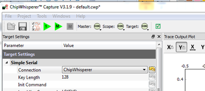
- Switch to the Target Settings tab, and as the connection, select the ChipWhisperer option (assuming you are using the Capture-Rev2)
- Press the Master Connect button again (or scope+target separately). You should end up with BOTH the scope and target connected:
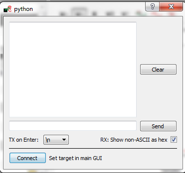
- From the Tools menu select Open Terminal, and press Connect on the terminal:
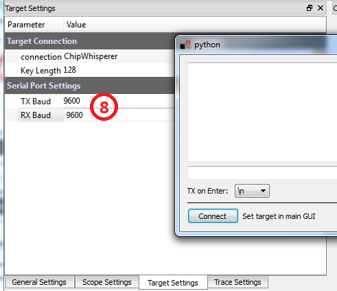
- Switch back to the Target Settings tab, without closing the terminal window. Set the baud rate for both TX & RX to
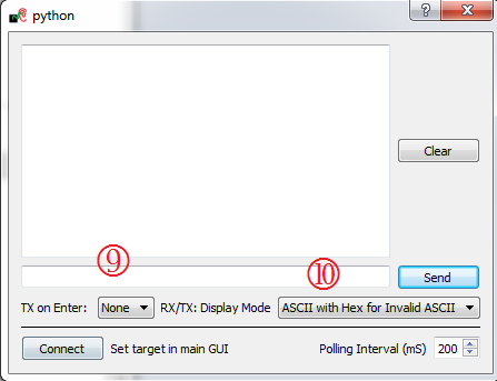
9600baud. Once you start using the terminal these values will switch to the actual baud rates in use (the hardware can only generate certain baud rates). You cannot use higher bauds for this tutorial as the combined error from the AVR code & ChipWhisperer serial port causes communications failures. - In the ChipWhisperer-Serial Terminal, change the TX on Enter to None, as we don't want to send any character to terminate a string.
- In the ChipWhisperer-Serial Terminal, set display mode to ASCII with Hex for Invalid ASCII if not already set.
- Finally send the command
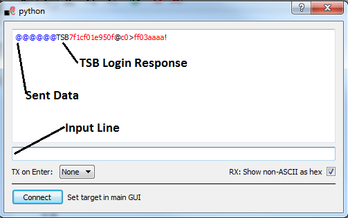
@@@, which is the login sequence for the TinySafeBoot bootloader. Simply type this in the input line, and press 'enter' to send. You will see the@@@echoed on the received data in a blue font. - The objective is to get the login response. You may have to send
@@@a few times for this to be successful, the following figure shows an example where the the login worked after sending a second round of@@@. You might get an invalid response your first time for example. The response should start withTSB:
| Byte Num | Value | Description |
|---|---|---|
| 1-3 | 'TSB' | Fixed string |
| 4-5 | 0x1C7F | Word indicating FW build |
| 6 | 0xF0 | TSB Status |
| 7 | 0x1E | AVR Signature Byte |
| 8 | 0x95 | AVR Signature Byte |
| 9 | 0x0F | AVR Signature Byte |
| 10 | 0x40 | Page Size in word |
| 11-12 | 0x3EC0 | App Flash size in words |
| 13-14 | 0x03FF | EEPROM Size in Bytes |
| 15-16 | 0xAAAA | Fixed Byte Sequence |
| 17 | '!' | Confirmation Character |
Finally, we want to monitor power when sending this sequence to the device. We'll need to configure a number of OpenADC settings for this. The following table shows these settings, please carefully go though and set each of these as given. Pay attention to the 'notes' section which has some additional information.
| Group | Item | Value | Note |
|---|---|---|---|
| Gain Setting | Setting | 40 | |
| Trigger Setup | Mode | falling edge | |
| Trigger Setup | Timeout | 7 | Adjust as needed - gives you time to type in the other window |
| ADC Clock | Source | EXTCLK x1 via DCM | Will need to reset DCM later |
| CW-Extra --> Trigger Pins | Front Panel A | Unchecked | |
| CW-Extra --> Trigger Pins | Target IO1 | Checked | Only 'Target IO1 (Serial TXD)' should be checked |
| CW-Extra | Clock Source | Target IO-IN | Confirm 'Freq Counter' reads 7.37MHz in 'ADC Clock' |
| ADC Clock | Reset ADC DCM | Click Button | Confirm 'ADC Freq' is 7.37MHz, and 'DCM Locked' is checked |
| after pressing button. |
- Before attacking the real system, we'll need to confirm these settings will work. To do so we'll monitor the power consumption whilst operating the bootloader under normal conditions.
- Switch to the Target Tab, and ERASE the Load Key Command, Go Command', and Output Format labels. This will mean the system will not send unexpected data:
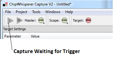
- With our system running, push the 'Capture 1' button. Notice it will go grey indicating the system is waiting for the trigger to occur:
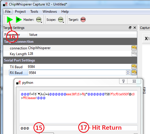
- Prepare the serial window by typing
@@@as before, but do not hit enter yet. We'll need to hit enter only after we arm the system. - Arm the system by pressing the 'Capture 1' button.
- Before the capture times out (e.g. before the button stops being gray), quickly click on the serial terminal output line and press 'Enter' to send the command, or press the 'Send' button beside the terminal output line to send the #:
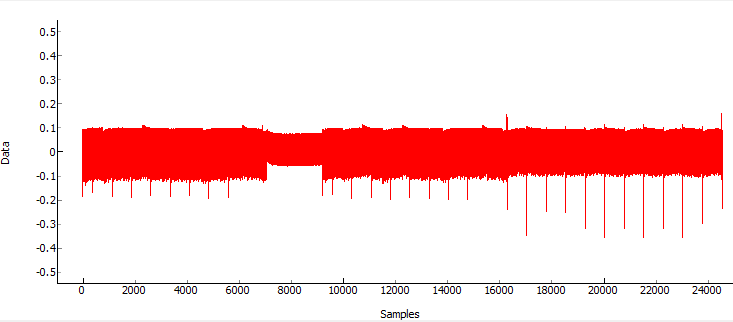
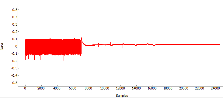
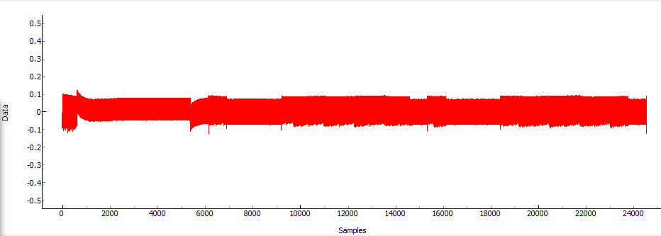
@@@command. Note you can adjust the timeout in the Trigger Setup group of the Scope Settings. - If this works, you will see the power consumption on receiving the command. You'll notice two distinct power signatures, which may look something like this:
- Or:
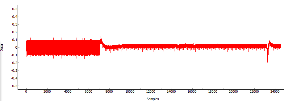
- The scale on the bottom is in samples. Remember we set the sample clock to 7.37 MHz (same speed of the device), meaning each sample represents 1 / 7.37E6 = 135.6nS. Our serial interface is running at approximately 9600 baud, meaning a single bit takes 1/9600 = 0.1042mS. Every byte requires 10 bits (1 start bit, 8 data bits, 1 stop bit), meaning a single byte over the UART represents 1.042mS, or 7684 samples. Note that in the second figure the power consumption drops dramatically after 7000 samples, which would correspond to a single byte being received (remember we triggered the capture based on the start bit).
- The two power traces represent two different modes in the bootloader. In the first power trace the bootloader is waiting for the login sequence, and receives all three bytes of it before awaiting the next command. In the second power trace the bootloader is already waiting the command byte. Since
@is not a valid command, when the bootloader receives the first@it simply jumps to the user program. The flash here is empty, which effectively performsnoptype operations. You can see a dramatic reduction in power as soon as the microcontroller stops receiving the data. - Be aware that the data begin sent in both cases is the exact same! The power consumption differences are solely because the microcontroller stops processing the incoming data. We'll exploit this to break a secret password in the final part of this experiment.
Setting a Password on the Bootloader
The TinySafeBoot bootloader allows us to set a password. Doing so requires us to send a binary blob to the device - something which we cannot do through a normal ASCII serial interface. This section will demonstrate how to use the command-line interface of the ChipWhisperer-Capture software to perform advanced operations with Python.
This section assums you still have the setup from the previous part running. If you have closed the program, perform steps 1 - 11 again (you don't need to configure the OpenADC settings).
- Close the ChipWhisperer-Serial Terminal window.
Switch to the Python Console on the bottom. You can enter commands in the bottom line & hit enter to have them executed:
As a test try just entering
self, which is a Python reference to the ChipWhisperer object. You can explore other options & Python will report the data-type, for example:>>> self <__main__.CWCaptureGUIobject at 0x05E27800> <chipwhisperer.capture.targets.simpleserial_readers.cw.SimpleSerial_ChipWhisperer object at 0x06E61030>
You can also call methods. For example we can send a string with the following:
>>> self.api.getTarget().ser.write("@@@")And to retreive the data we would call the read() function, where we specify the number of bytes to attempt to read. As before if we fail to get a response you may need to resend the "@@@" prompt:
>>>  self.api.getTarget().ser.write("@@@")

>>> self.api.getTarget().ser.read(255)
u''
>>> self.api.getTarget().ser.write("@@@")
>>> self.api.getTarget().ser.read(255)
u'TSB\x7f\x1c\xf0\x1e\x95\x0f@\xc0>\xff\x03\xaa\xaa!'
To make typing easier, create variables that point to the read and write functions:
>>> read = self.api.getTarget().ser.read
>>> write = self.api.getTarget().ser.write
- To set the bootloader on TSB, we need to modify a special page of FLASH memory. First, ensure you've recently (e.g. within < 30 seconds) received the
TSBsignon prompt. If not resend the@@@string until the call toread(255)returns theTSBprompt. You should read the next step before doing this however. Send the command 'c' to read the last page of flash. Rather than printing to console, simply save this to a variable:
>>> write('c')
>>> lastpage = read(255)
>>> lastpage
u'\xff\xff\xff\xff\xff\xff\xff\xff\xff\xff\xff\xff\xff\xff\xff\xff\xff\xff\xff\xff\xff\xff\xff\xff\xff
\xff\xff\xff\xff\xff\xff\xff\xff\xff\xff\xff\xff\xff\xff\xff\xff\xff\xff\xff\xff\xff\xff\xff\xff\xff\xff
\xff\xff\xff\xff\xff\xff\xff\xff\xff\xff\xff\xff\xff\xff\xff\xff\xff\xff\xff\xff\xff\xff\xff\xff\xff\xff
\xff\xff\xff\xff\xff\xff\xff\xff\xff\xff\xff\xff\xff\xff\xff\xff\xff\xff\xff\xff\xff\xff\xff\xff\xff\xff
\xff\xff\xff\xff\xff\xff\xff\xff\xff\xff\xff\xff\xff\xff\xff\xff\xff\xff\xff\xff\xff\xff\xff\xff\xff!'
Success! You've managed to read the space where we'll store the user password. First, we need to now remove the trailing 'CONFIRM' character from the end, leaving us with a complete page:
>>> lastpage = lastpage[:-1]
Next, you should convert this to a bytearray which will make modifications easier. When converting we need to specify a character set as well:
>>> lastpage = bytearray(lastpage, 'latin-1')
You can now retreive individual bytes of the array & get the associated value:
>>> lastpage[2]
255
Finally, let's set a two-character password of 'ce'. The password starts at offset 3, and is terminated by a 0xFF:
>>> lastpage[3] = ord('c')
>>> lastpage[4] = ord('e')
>>> lastpage[5] = 255
Because we are using bytearrays, we needed to use the
ord()function to get the integer value associated with each character. We could have more directly written the password in if we had kept the original encoding. But often you need to modify byte-level values, meaning thebytearray()conversion is a useful tool to know.Finally we can write this back to the system. We need to send two commands to do this:
>>> write('C')
>>> write('!')
>>> write(lastpage.decode('latin-1'))
>>> read(255)
u'?\xff\xff\xffce\xff\xff\xff\xff\xff\xff\xff\xff\xff\xff\xff\xff\xff\xff\xff\xff\xff\xff\xff\xff\xff\xff\xff\xff\xff\xff\xff\xff\xff\xff\xff
\xff\xff\xff\xff\xff\xff\xff\xff\xff\xff\xff\xff\xff\xff\xff\xff\xff\xff\xff\xff\xff\xff\xff\xff\xff\xff\xff\xff\xff\xff\xff\xff\xff\xff\xff
\xff\xff\xff\xff\xff\xff\xff\xff\xff\xff\xff\xff\xff\xff\xff\xff\xff\xff\xff\xff\xff\xff\xff\xff\xff\xff\xff\xff\xff\xff\xff\xff\xff\xff\xff
\xff\xff\xff\xff\xff\xff\xff\xff\xff\xff\xff\xff\xff\xff\xff\xff\xff\xff\xff\xff\xff\xff!'
>>> write('c')
>>> read(255)
u'\xff\xff\xffce\xff\xff\xff\xff\xff\xff\xff\xff\xff\xff\xff\xff\xff\xff\xff\xff\xff\xff\xff\xff\xff\xff\xff\xff\xff\xff\xff\xff\xff\xff\xff
\xff\xff\xff\xff\xff\xff\xff\xff\xff\xff\xff\xff\xff\xff\xff\xff\xff\xff\xff\xff\xff\xff\xff\xff\xff\xff\xff\xff\xff\xff\xff\xff\xff\xff\xff
\xff\xff\xff\xff\xff\xff\xff\xff\xff\xff\xff\xff\xff\xff\xff\xff\xff\xff\xff\xff\xff\xff\xff\xff\xff\xff\xff\xff\xff\xff\xff\xff\xff\xff\xff
\xff\xff\xff\xff\xff\xff\xff\xff\xff\xff\xff\xff\xff\xff\xff\xff\xff\xff\xff\xff\xff\xff!'
Confirm that the
cesequence occurs at the start. If something else appears you may have the wrong password set in the device!We now have a bootloader with a password protection. Be aware that if you enter the wrong password you will cause the bootloader to spin into an infinite loop! You can check the password (carefully) by executing the following commands:
   >>> write('q')
   >>> write('@@@')
   >>> read(255)
   u''
   >>> write('ce')
   >>> read(255)
   u'TSBx7fx1cxf0x1ex95x0f@xc0>xffx03xaaxaa!'
The
qcommand causes the bootloader to quit & jump to the application. Since there is no application it re-enters the bootloader. The@@@is our standard sign-on sequence. However the bootloader waits for the secret password before transmitting the sign-on sequence. Note how it's only after sendingcethat the bootloader works.
Enabling the Reset
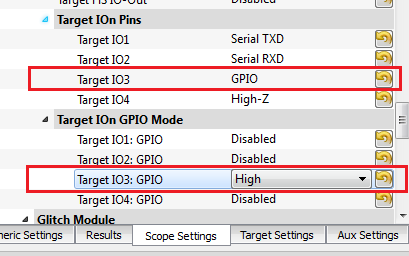
Finally, we'll reuse the pin GPIO3 as a reset pin. To perform this:
Scripting the Setup
At this point we want to script the setup of the ChipWhisperer-Capture tool, along with pulling in our special utility which is capable of resetting the AVR microcontroller.
from chipwhisperer.common.api.CWCoreAPI import CWCoreAPI  # Import the ChipWhisperer API
from chipwhisperer.common.scripts.base import UserScriptBase
import time

class UserScript(UserScriptBase):
    def __init__(self, api):
        super(UserScript, self).__init__(api)

    def resetAVR(self):
        self.api.setParameter(['CW Extra Settings', 'Target IOn GPIO Mode', 'Target IO3: GPIO', 'Low'])
        time.sleep(0.05)
        self.api.setParameter(['CW Extra Settings', 'Target IOn GPIO Mode', 'Target IO3: GPIO', 'High'])

    def run(self):
        #User commands here
        self.api.setParameter(['Generic Settings', 'Scope Module', 'ChipWhisperer/OpenADC'])
        self.api.setParameter(['Generic Settings', 'Target Module', 'Simple Serial'])
        self.api.setParameter(['Simple Serial', 'Connection', 'ChipWhisperer'])
        self.api.setParameter(['ChipWhisperer/OpenADC', 'Connection', 'ChipWhisperer Rev2'])

        self.api.connect()


        #Example of using a list to set parameters. Slightly easier to copy/paste in this format
        self.api.setParameter(['Simple Serial', 'ChipWhisperer', 'TX Baud', 9600])
        self.api.setParameter(['Simple Serial', 'ChipWhisperer', 'RX Baud', 9600])
        self.api.setParameter(['CW Extra Settings', 'Target IOn Pins', 'Target IO3', 'GPIO'])
        self.api.setParameter(['CW Extra Settings', 'Target IOn GPIO Mode', 'Target IO3: GPIO', 'High'])

        #Assign to API for hacking together tests
        self.api.resetAVR = self.resetAVR

        #Some useful commands to play with from GUI
        #self.resetAVR()
        #ser = self.api.getTarget().ser
        #ser.write("@@@")
        #ser.write("ce")
        #print ser.read(255)


if __name__ == '__main__':
    import chipwhisperer.capture.ui.CWCaptureGUI as cwc         # Import the ChipWhispererCapture GUI
    from chipwhisperer.common.utils.parameter import Parameter  # Comment this line if you don't want to use the GUI
    Parameter.usePyQtGraph = True                               # Comment this line if you don't want to use the GUI
    api = CWCoreAPI()                                           # Instantiate the API
    app = cwc.makeApplication("Capture")                        # Change the name if you want a different settings scope
    gui = cwc.CWCaptureGUI(api)                                 # Comment this line if you don't want to use the GUI
    gui.show()                                                  # Comment this line if you don't want to use the GUI
    api.runScriptClass(UserScript)                              # Run the User Script (executes "run()" by default)
    app.exec_()                                                 # Comment this line if you don't want to use the GUI
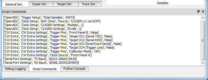
This is a basic 'script', which is really just a Python program using the ChipWhisperer library. Save the script to a file & run this, which should open the ChipWhisperer-Capture window as before. Finally, let's once again configure the OpenADC for analog capture. Before doing this, switch to the Script Commands tab, and note there is already some script information being printed. We will make changes to the system and then observe additional data that gets printed here:
</li>Follow step 13 from section testingserialbasic, which contains a number of settings for the OpenADC portion. After performing the commands, you will note that additional steps have been printed to the Script Commands window. For example your output might look something like this:
        ['OpenADC', 'Gain Setting', 'Setting', 45],
        ['OpenADC', 'Trigger Setup', 'Mode', 'falling edge'],
        ['OpenADC', 'Clock Setup', 'ADC Clock', 'Source', 'EXTCLK x1 via DCM'],
        ['CW Extra Settings', 'Trigger Pins', 'Front Panel A', False],
        ['CW Extra Settings', 'Trigger Pins', 'Target IO1 (Serial TXD)', True],
        ['CW Extra Settings', 'Clock Source', 'Target IO-IN'],
        ['OpenADC', 'Clock Setup', 'ADC Clock', 'Reset ADC DCM', None],
        ['Simple Serial', 'Output Format', u''],
        ['Simple Serial', 'Go Command', u''],
        ['Simple Serial', 'Load Key Command', u''],]
Note the format __changes slightly between releases__, and using the wrong format will cause errors. Thus you should copy the output from your specific application and note the exact list used here.
Insert these commands into our master script such we don't need to perform any manual configuration. Close the ChipWhisperer-Capture window, and find the following line in your script:
#Connect to scope
self.api.connect()
Copy and paste the list of commands into the script just below that:
#Connect to scope
self.api.connect()

        ['OpenADC', 'Gain Setting', 'Setting', 45],
        ['OpenADC', 'Trigger Setup', 'Mode', 'falling edge'],
        ['OpenADC', 'Clock Setup', 'ADC Clock', 'Source', 'EXTCLK x1 via DCM'],
        ['CW Extra Settings', 'Trigger Pins', 'Front Panel A', False],
        ['CW Extra Settings', 'Trigger Pins', 'Target IO1 (Serial TXD)', True],
        ['CW Extra Settings', 'Clock Source', 'Target IO-IN'],
        ['OpenADC', 'Clock Setup', 'ADC Clock', 'Reset ADC DCM', None],
        ['Simple Serial', 'Output Format', u''],
        ['Simple Serial', 'Go Command', u''],
        ['Simple Serial', 'Load Key Command', u''],
Convert the list into a Python list variable with a name, which is done by inserting a cmds = [ on the line above, a , after each line, and a ] after the final line:
#Connect to scope
self.api.connect()

cmds = [
        ['OpenADC', 'Gain Setting', 'Setting', 45],
        ['OpenADC', 'Trigger Setup', 'Mode', 'falling edge'],
        ['OpenADC', 'Clock Setup', 'ADC Clock', 'Source', 'EXTCLK x1 via DCM'],
        ['CW Extra Settings', 'Trigger Pins', 'Front Panel A', False],
        ['CW Extra Settings', 'Trigger Pins', 'Target IO1 (Serial TXD)', True],
        ['CW Extra Settings', 'Clock Source', 'Target IO-IN'],
        ['OpenADC', 'Clock Setup', 'ADC Clock', 'Reset ADC DCM', None],
        ['Simple Serial', 'Output Format', u''],
        ['Simple Serial', 'Go Command', u''],
        ['Simple Serial', 'Load Key Command', u''],
]
Add a loop to run each command on the system:
#Connect to scope
self.api.connect()

cmds = [
        ['OpenADC', 'Gain Setting', 'Setting', 45],
        ['OpenADC', 'Trigger Setup', 'Mode', 'falling edge'],
        ['OpenADC', 'Clock Setup', 'ADC Clock', 'Source', 'EXTCLK x1 via DCM'],
        ['CW Extra Settings', 'Trigger Pins', 'Front Panel A', False],
        ['CW Extra Settings', 'Trigger Pins', 'Target IO1 (Serial TXD)', True],
        ['CW Extra Settings', 'Clock Source', 'Target IO-IN'],
        ['OpenADC', 'Clock Setup', 'ADC Clock', 'Reset ADC DCM', None],
        ['Simple Serial', 'Output Format', u''],
        ['Simple Serial', 'Go Command', u''],
        ['Simple Serial', 'Load Key Command', u''],
]

for cmd in cmds: self.api.setParameter(cmd)Switch to the Python console in the running ChipWhisperer-Capture application. First create a shortcut for the serial port:
>>> ser = self.api.getTarget().ser
Then run the following commands:
>>> self.api.resetAVR()
>>> ser.write("@@@")
At this point the system is waiting for a correct password. Put the following text into the Python console but do not hit enter yet:
ser.write("ce")With the ser.write("ce") still not yet sent, hit the Capture 1 button. Then hit enter on the Python console to send the ser.write("ce") command. The system should trigger immediatly and capture a power trace, which might look something like this:
To re-run the capture, perform the same sequence of commands in steps 8 & 9. You should get an almost identical trace each time you do this.
Now perform the same sequence (e.g. self.api.resetAVR(), ser.write("@@@")). But instead of sending the correct password "ce", send an incorrect password such as "ff". You should now see a power trace such as this:
Notice the start difference! You can examin the bootloader source to get an idea why this occurs. In particular the portion dealing with the password check looks like this:
CheckPW:
chpw1:
        lpm tmp3, z+                    ; load character from Flash
        cpi tmp3, 255                   ; byte value (255) indicates
        breq chpwx                      ; end of password -> exit
        rcall Receivebyte               ; else receive next character
chpw2:
        cp tmp3, tmp1                   ; compare with password
        breq chpw1                      ; if equal check next character
        cpi tmp1, 0                     ; or was it 0 (emergency erase)
chpwl:  brne chpwl                      ; if not, loop infinitely
        rcall RequestConfirmation       ; if yes, request confirm
Note as soon as you get a wrong character, the reception of characters stops.
Perform the same experiment, but send the first character right and the second character wrong. So send "cf" for example as the password:
>>> self.api.resetAVR()
>>> ser.write("@@@")
---Push Capture 1 Button---
>>> ser.write("cf")
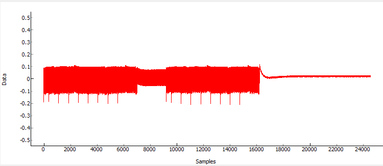
The results will again have a sharp drop in power after the reception of the second character:
Thus by looking at the power consumption, we can determine the wrong password character. This makes it possible to brute-force the password, since we can simply guess a single digit of the password at a time.
Conclusion
This tutorial has demonstrated the use of the power side-channel for performing timing attacks. A simple proof-of-concept is performed against a bootloader, although a complete example is not presented. It is left as an exercise to the reader to script a complete attack for this example.
