| As of August 2020 the site you are on (wiki.newae.com) is deprecated, and content is now at rtfm.newae.com. |
Difference between revisions of "V3:Tutorial B10 Using with SASEBO-W CardOS or DPA Contest v4.2"
(Created page with "= Tutorial #B10: Using with SASEBO-W CardOS or DPA Contest v4.2 = == Background == A number of extremely useful tools for side channel analysis are distributed by Morita Tec...") |
(No difference)
|
Revision as of 15:14, 24 September 2017
Tutorial #B10: Using with SASEBO-W CardOS or DPA Contest v4.2
Background
A number of extremely useful tools for side channel analysis are distributed by Morita Tech Co., Ltd under the SAKURA project name. In fact much the original ChipWhisperer system was developed on these tools, and a great debt is owed to Akashi Satoh for this development.
This tutorial will demonstrate how the ChipWhisperer system can be used in tandem with the SASEBO-W system. The first part of this tutorial will target the same ATMegaCard used by the SASEBO-W, and the second part of the tutorial will demonstrate how the ATMega328p can be connected to the SASEBO-W using the interposer board.
Hardware Setup
About the ATMega Card
The ATMega Card is shown below:
This card contains an Atmel ATMega163 die along with a 24C256 EEPROM. You can see the internal pinout of these cards online. It should be noted that this card is in a SmartCard form factor, but is essentially just a very old microcontroller (AtMega163). If you are unable to find this card but still wish to perform these experiments, there are two other options:
# Purchase an ATMega16, which can be programmed with the ATMega163 binary (.hex file). See an Atmel App-Note on the subject. The AtMega16 will not fit on the Multi-Target board, meaning you must build your own board. You can then connect the appropriate IO lines to the SmartCard interface.
- Rebuild your code for the ATMega328p. This should require minimal changes to the source code, but note you cannot program a .hex file for a Mega163 into a Mega328P directly. You will need the complete source code.
Alternatively of course you can package your target algorithm into something like the demo SimpleSerial project too. There is no real need to use the SmartCard APDU format, and the interface tends to be much slower on the ChipWhisperer system.
Programming
You will need an image to program into the SmartCard. This tutorial uses the SASEBO-W Card OS. Details of this are available from the SASEBO-W Page. Download the file entitled Smartcard sample binary for ATMega 163, which is described in the document entitled SASEBO-W Smart Card OS Specification Ver. 0.4-5.
The first file will have a .hex inside it, which you must program using AVRStudio or similar. To use the built-in programmer, the following connections should be set:
# Remove all jumpers from the AVR and XMEGA sections of the MultiTarget board.
- Remove the AtMega328p from the socket.
- Set the oscillator for 3.579 MHz (JP18), and set the CLKOSC jumper (JP17).
- Mount all four jumpers on the AVR-PROG section (JP8).
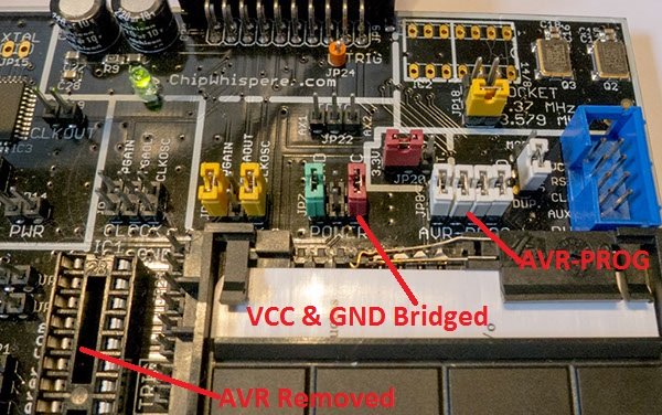
- Shunt both the GND and VCC resistors, as the programming will fail with those resistors in the power lines (JP7).
The following image shows these connections:
Then use AVRStudio to program the .hex file. The instructions for doing this are as in Installing_ChipWhisperer#Getting_AVR_Compiler_Toolchain, however when selecting the AVR type select ATMega163 instead of ATMega328p. Check the Read Signature option works, if not double-check the above hardware connections.
Hardware setup for using Card Socket
The following describes the jumper settings when using the SmartCard socket on the MultiTarget Victim Board:
# NO jumpers mounted in XMEGA Portion or AVR Portion, ideally remove the AVR Chip as well
- 3.3V IO Level (JP20 set to INT.)
- The 3.579 MHz oscillator is selected as the CLKOSC source (JP18)
- The CLKOSC is connected to the SmartCard Clock Network, along with connected to the FPGAIN pin (JP4)
- #; Trigger is selected as AX2 (JP22) [NOTE: The silkscreen on the multi-target board is incorrect - this is actually the AUX1 pin. This tutorial will
- use the silkscreen notation instead of the actual pin for jumper settings]
- Power measurement taken from VCC shunt (JP7)
- Jumpers removed from the AVR-PROG header (JP8)
- Connect the GPIO1 line to the RESET line. This is done with a jumper from a line labeled RXD on the AVR section to one of the pins on the AVR-PROG section. Note you can alternatively connect this line to the RST pin on the blue 8-pin smartcard connector header.
The following image shows this setup:
Connect the 20-pin cable and SMA cable if not already connected, and plug your programmed MegaCard into the SmartCard socket. This completes the hardware setup when using the card socket.
Hardware Setup using ATMega16
The AtMega16 is binary-compatible with the AtMega163, meaning a hex file for the ATMega163 can be programmed directly into the ATMega16. Assuming you have the SASEBO-W adapter, this simple schematic shows the required circuit:
Note that we are not using the shunt on the SASEBO-W, as we have added filtering capacitors. Due to the long ribbon cable (with a high-frequency clock), you'll end up with a lot of noise if you attempted to use the shunt on the SASEBO-W (which means no filtering caps on the AtMega16). The implementation looks like this:
You'll have to program the AtMega16 device, which you can do as described in the SASEBO-W Quickstart guide. The only difference is you'll need to change the device to the mega16. You'll also need to program the fuse bits, as by default the ATMega16 uses an internal oscillator, which has the wrong frequency for the SASEBO-W communications.
Here's an example of the batch file which will program the ATMega16, along with programming the fuse bytes. You only need to program the fuse bytes the first time you use this, otherwise you can just program the .hex file:
avrdude -c sasebow -p m16 -P ft0 -B 115200 -u -e -U flash:w:AES.hex:a -U lfuse:w:0xD0:m -U hfuse:w:0x99:m -v
pause
Hardware Setup using ATMega328p
See SASEBO-W_Target#Connecting_the_Multi-Target_Board_to_the_SASEBO-W for details of connecting the Multi-Target board to the SASEBO-W.
Software Setup and Example Capture (CardOS)
# Run the ChipWhisperer Capture software
- Select the following options on the General Settings tab:
- Scope Module: ChipWhisperer/OpenADC
- Target Module: Smart Card
- Trace Format: ChipWhisperer/Native
- Switch to the Target Settings tab. Set the following two options:
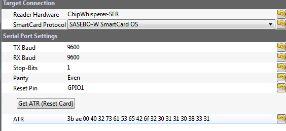
- Reader Hardware: ChipWhisperer-SER (NOTE: This is new a new option as of 0.09, the old ChipWhisperer-USI is not recommended anymore)
- SmartCard Protocol: SASEBO-W SmartCard OS
Press the Master Connect button, the scope and target should both show as connected:
- Under the Scope Settings tab, make the following changes:
- OpenADC-->Gain-->Setting: 35
- OpenADC-->Trigger Setup-->Mode: Rising Edge
- CW Extra-->Clock Source: TargetIO-IN
- CW Extra-->Trigger Pins: Uncheck Front Panel A
- CW Extra-->Trigger Pins: Check Target IO4 (Trigger Line)
- OpenADC-->Clock Setup-->ADC Clock-->Source: EXTCLK x4 via DCM
- Press the Reset ADC DCM button in that area, confirm the ADC Freq reads 14.3 MHz indicating the clock routing is working.
- OpenADC-->Trigger Setup-->Total Samples: 5000
Changes for DPAContest v4.2 Card
As of ChipWhisperer Release 0.09, the DPAContest v4.2 protocol is also supported. This protocol uses AES-128 RSM, making an interesting attack of a protected target. The following details settings required to attack this card.
# Change the TRIG jumper to AX1 instead of AX2 (again this is based on silkscreen markings)
- In step 3-b above: Select the DPA Contest 4.2 as the SmartCard Protocol
Otherwise you can follow the above example. With those settings, and the .hex and .eeprom file programmed into the card. Note the ATR does not seem to work properly, possibly as it is sent too soon after reset for the ChipWhisperer reader to capture.
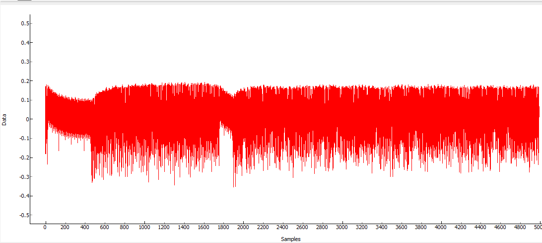
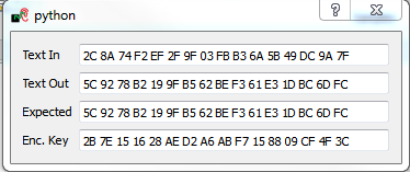
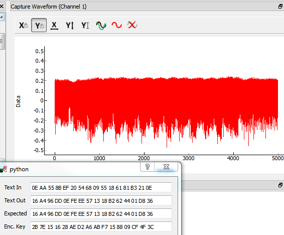
You should see a power signature that looks something like this, note again the use of the encryption monitor to confirm correct operation:

