| As of August 2020 the site you are on (wiki.newae.com) is deprecated, and content is now at rtfm.newae.com. |
Difference between revisions of "Tutorial A5 Breaking AES-256 Bootloader"
| Line 200: | Line 200: | ||
[[File:A5_pp_resync_end.png|400px]]}} | [[File:A5_pp_resync_end.png|400px]]}} | ||
| − | === | + | ==== Continuing the Attack ==== |
The next step is to program our own leakage model. The following Python code models the Hamming weight model of the 13th round S-box: | The next step is to program our own leakage model. The following Python code models the Hamming weight model of the 13th round S-box: | ||
| Line 269: | Line 269: | ||
== Appendix A: Target Code == | == Appendix A: Target Code == | ||
| − | < | + | <syntaxhighlight lang=python> |
#!/usr/bin/python | #!/usr/bin/python | ||
# -*- coding: utf-8 -*- | # -*- coding: utf-8 -*- | ||
| Line 503: | Line 503: | ||
else: | else: | ||
raise IOError("Failed to communicate, no response") | raise IOError("Failed to communicate, no response") | ||
| − | </ | + | </syntaxhighlight> |
== Appendix B: Capture Script == | == Appendix B: Capture Script == | ||
| Line 512: | Line 512: | ||
# Set the 'Target Module' as 'AES Bootloader' (you need to have that target on your system) | # Set the 'Target Module' as 'AES Bootloader' (you need to have that target on your system) | ||
| − | < | + | <syntaxhighlight lang=python> |
"""Setup script for CWLite/1200 with XMEGA (CW303/CW308-XMEGA/CWLite target) | """Setup script for CWLite/1200 with XMEGA (CW303/CW308-XMEGA/CWLite target) | ||
specifically for Tutorial A5: the AES-256 bootloader attack | specifically for Tutorial A5: the AES-256 bootloader attack | ||
| Line 532: | Line 532: | ||
scope.io.tio2 = "serial_tx" | scope.io.tio2 = "serial_tx" | ||
scope.io.hs2 = "clkgen" | scope.io.hs2 = "clkgen" | ||
| − | </ | + | </syntaxhighlight> |
== Appendix C: AES-256 14th Round Key Script == | == Appendix C: AES-256 14th Round Key Script == | ||
Revision as of 12:27, 10 October 2018
This tutorial has been updated for ChipWhisperer 4.0.0 release. If you are using 3.x.x see the "V3" link in the sidebar.
| A5: Breaking AES-256 Bootloader | |
|---|---|
| Target Architecture | XMEGA/Arm |
| Hardware Crypto | No |
| Software Release | V3 / V4 / V5 |
This tutorial will take you through a complete attack on an encrypted bootloader using AES-256. This demonstrates how to using side-channel power analysis on practical systems, along with discussing how to perform analysis with custom scripts.
Whilst the tutorial assumes you will be performing the entire capture of traces along with the attack, it is possible to download the traces if you don't have the hardware, in which case skip section #Setting up the Hardware and #Capturing the Traces.
Contents
- 1 Background
- 2 Building the Firmware
- 3 Setting up the Hardware
- 4 Programming the Target
- 5 Capturing the Traces
- 6 Finding the Encryption Key
- 7 Next Steps
- 8 Appendix A: Target Code
- 9 Appendix B: Capture Script
- 10 Appendix C: AES-256 14th Round Key Script
- 11 Appendix D: AES-256 13th Round Key Script
- 12 Links
Background
In the world of microcontrollers, a bootloader is a special piece of firmware that is made to let the user upload new programs into memory. This is especially useful for devices with complex code that may need to be patched or otherwise updated in the future - a bootloader makes it possible for the user to upload a patched version of the firmware onto the micro. The bootloader receives information from a communication line (a USB port, serial port, ethernet port, WiFi connection, etc...) and stores this data into program memory. Once the full firmware has been received, the micro can happily run its updated code.
There is one big security issue to worry about with bootloaders. A company may want to stop their customers from writing their own firmware and uploading it onto the micro. For example, this might be for protection reasons - hackers might be able to access parts of the device that weren't meant to be accessed. One way of stopping this is to add encryption. The company can add their own secret signature to the firmware code and encrypt it with a secret key. Then, the bootloader can decrypt the incoming firmware and confirm that the incoming firmware is correctly signed. Users will not know the secret key or the signature tied to the firmware, so they won't be able to "fake" their own.
This tutorial will work with a simple AES-256 bootloader. The victim will receive data through a serial connection, decrypt the command, and confirm that the included signature is correct. Then, it will only save the code into memory if the signature check succeeded. To make this system more robust against attacks, the bootloader will use cipher-block chaining (CBC mode). Our goal is to find the secret key and the CBC initialization vector so that we could successfully fake our own firmware.
Bootloader Communications Protocol
The bootloader's communications protocol operates over a serial port at 38400 baud rate. The bootloader is always waiting for new data to be sent in this example; in real life one would typically force the bootloader to enter through a command sequence.
Commands sent to the bootloader look as follows:
       |<-------- Encrypted block (16 bytes) ---------->|
       |                                                |
+------+------+------+------+------+------+ .... +------+------+------+
| 0x00 |    Signature (4 Bytes)    |  Data (12 Bytes)   |   CRC-16    |
+------+------+------+------+------+------+ .... +------+------+------+
This frame has four parts:
-
0x00: 1 byte of fixed header - Signature: A secret 4 byte constant. The bootloader will confirm that this signature is correct after decrypting the frame.
- Data: 12 bytes of the incoming firmware. This system forces us to send the code 12 bytes at a time; more complete bootloaders may allow longer variable-length frames.
- CRC-16: A 16-bit checksum using the CRC-CCITT polynomial (0x1021). The LSB of the CRC is sent first, followed by the MSB. The bootloader will reply over the serial port, describing whether or not this CRC check was valid.
As described in the diagram, the 16 byte block is not sent as plaintext. Instead, it is encrypted using AES-256 in CBC mode. This encryption method will be described in the next section.
The bootloader responds to each command with a single byte indicating if the CRC-16 was OK or not:
            +------+
CRC-OK:     | 0xA1 |
            +------+

            +------+
CRC Failed: | 0xA4 |
            +------+
Then, after replying to the command, the bootloader veries that the signature is correct. If it matches the expected manufacturer's signature, the 12 bytes of data will be written to flash memory. Otherwise, the data is discarded.
Details of AES-256 CBC
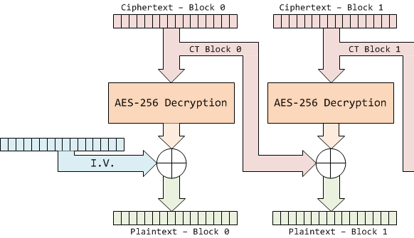
The system uses the AES algorithm in Cipher Block Chaining (CBC) mode. In general one avoids using encryption 'as-is' (i.e. Electronic Code Book), since it means any piece of plaintext always maps to the same piece of ciphertext. Cipher Block Chaining ensures that if you encrypted the same thing a bunch of times it would always encrypt to a new piece of ciphertext.
You can see another reference on the design of the encryption side; we'll be only talking about the decryption side here. In this case AES-256 CBC mode is used as follows, where the details of the AES-256 Decryption block will be discussed in detail later:
This diagram shows that the output of the decryption is no longer used directly as the plaintext. Instead, the output is XORed with a 16 byte mask, which is usually taken from the previous ciphertext. Also, the first decryption block has no previous ciphertext to use, so a secret initialization vector (IV) is used instead. If we are going to decrypt the entire ciphertext (including block 0) or correctly generate our own ciphertext, we'll need to find this IV along with the AES key.
Attacking AES-256
The system in this tutorial uses AES-256 encryption, which has a 256 bit (32 byte) key - twice as large as the 16 byte key we've attacked in previous tutorials. This means that our regular AES-128 CPA attacks won't quite work. However, extending these attacks to AES-256 is fairly straightforward: the theory is explained in detail in Extending AES-128 Attacks to AES-256.
As the theory page explains, our AES-256 attack will have 4 steps:
- Perform a standard attack (as in AES-128 decryption) to determine the first 16 bytes of the key, corresponding to the 14th round encryption key.
- Using the known 14th round key, calculate the hypothetical outputs of each S-Box from the 13th round using the ciphertext processed by the 14th round, and determine the 16 bytes of the 13th round key manipulated by inverse MixColumns.
- Perform the MixColumns and ShiftRows operation on the hypothetical key determined above, recovering the 13th round key.
- Using the AES-256 key schedule, reverse the 13th and 14th round keys to determine the original AES-256 encryption key.
Building the Firmware
Are you following this tutorial at a training event? If so ONLY use the provided hex-file with secret key already embedded, do not rebuild the firmware!
For this example, we'll be using the bootloader-aes256 project.
Building for CWLite with XMEGA Target
You'll need to have installed avr-gcc and avr-libc. You may have already done this by following the installation guide, or if using the ChipWhisperer-VM it comes prepared with avr-gcc already setup. See the Installing_ChipWhisperer guide for details.
Once you have a working compiler (check by typing 'avr-gcc' at the command line - if using Windows you may need to setup a special batch file to provide you with a avr-gcc command prompt).
- We want to use the existing SimpleSerial firmware as a base for our project, but we don't want to edit the existing firmware. Instead, we'll make a new project with a copy of this firmware. Copy the directory of the firmware you want to modify in the
chipwhisperer/hardware/vicitims/firmwareto a new folder. The folder you copy will depend on what tutorial you're doing. Typically, the firmware you want to use is listed above the "Building for ..." drop down menus in this wiki. The name is arbitrary, but for this example, we'll call itsimpleserial-LAB-SPECIFIC-FOLDER(though depending on what firmware and tutorial you're working off of, you may want to call it something different). You must keep it in the same directory, as it will reference other files within that directory for the build process. - Open a terminal with avr-gcc in the path. If using Windows the sidebar on the Installing_ChipWhisperer page - you can either add WinAVR to your system path, or you can run the 'winavr.bat' file suggested.
Change the terminal to the newly copied directory. For example:
Windows:cd c:\chipwhisperer\hardware\victims\firmware\simpleserial-LAB-SPECIFIC-FOLDER
Linux/macOS:cd chipwhisperer/hardware/victims/firmware/simpleserial-LAB-SPECIFIC-FOLDER
Then, run
maketo build the system. Make sure you specify which platform you're using as your target. For example, for the ChipWhisperer Lite target, runmake PLATFORM=CW303
Which should have the following output:
...Bunch of lines removed...
Creating Extended Listing: simpleserial-base.lss
avr-objdump -h -S -z simpleserial-base.elf > simpleserial-base.lss

Creating Symbol Table: simpleserial-base.sym
avr-nm -n simpleserial-base.elf > simpleserial-base.sym

Size after:
AVR Memory Usage
----------------
Device: atxmega128d3

Program:    1524 bytes (1.1% Full)
(.text + .data + .bootloader)

Data:        224 bytes (2.7% Full)
(.data + .bss + .noinit)


Built for platform CW-Lite XMEGA

-------- end --------
Ensure that the "Built for platform ___" matches your target device.
=== Building for CWLite with XMEGA Target === You'll need to have installed avr-gcc and avr-libc. You may have already done this by following the installation guide, or if using the ChipWhisperer-VM it comes prepared with avr-gcc already setup. See the Installing_ChipWhisperer guide for details.
Once you have a working compiler (check by typing 'avr-gcc' at the command line - if using Windows you may need to setup a special batch file to provide you with a avr-gcc command prompt).
- We want to use the existing SimpleSerial firmware as a base for our project, but we don't want to edit the existing firmware. Instead, we'll make a new project with a copy of this firmware. Copy the directory of the firmware you want to modify in the
chipwhisperer/hardware/vicitims/firmwareto a new folder. The folder you copy will depend on what tutorial you're doing. Typically, the firmware you want to use is listed above the "Building for ..." drop down menus in this wiki. The name is arbitrary, but for this example, we'll call itsimpleserial-LAB-SPECIFIC-FOLDER(though depending on what firmware and tutorial you're working off of, you may want to call it something different). You must keep it in the same directory, as it will reference other files within that directory for the build process. - Open a terminal with avr-gcc in the path. If using Windows the sidebar on the Installing_ChipWhisperer page - you can either add WinAVR to your system path, or you can run the 'winavr.bat' file suggested.
Change the terminal to the newly copied directory. For example:
Windows:cd c:\chipwhisperer\hardware\victims\firmware\simpleserial-LAB-SPECIFIC-FOLDER
Linux/macOS:cd chipwhisperer/hardware/victims/firmware/simpleserial-LAB-SPECIFIC-FOLDER
Then, run
maketo build the system. Make sure you specify which platform you're using as your target. For example, for the ChipWhisperer Lite target, runmake PLATFORM=CW303
Which should have the following output:
...Bunch of lines removed...
Creating Extended Listing: simpleserial-base.lss
avr-objdump -h -S -z simpleserial-base.elf > simpleserial-base.lss

Creating Symbol Table: simpleserial-base.sym
avr-nm -n simpleserial-base.elf > simpleserial-base.sym

Size after:
AVR Memory Usage
----------------
Device: atxmega128d3

Program:    1524 bytes (1.1% Full)
(.text + .data + .bootloader)

Data:        224 bytes (2.7% Full)
(.data + .bss + .noinit)


Built for platform CW-Lite XMEGA

-------- end --------
Ensure that the "Built for platform ___" matches your target device.
Building for CWLite with Arm Target
You'll need to have installed the GNU Embedded Toolchain for ARM. If you haven't yet, see the Installing_ChipWhisperer guide, specifically the Installing ARM Toolchain section, for details.
Once you have a working compiler (check by typing 'arm-none-eabi-gcc' at the command line).
- We want to use the existing SimpleSerial firmware as a base for our project, but we don't want to edit the existing firmware. Instead, we'll make a new project with a copy of this firmware. Copy the directory of the firmware you want to modify in the
chipwhisperer/hardware/vicitims/firmwareto a new folder. The folder you copy will depend on what tutorial you're doing. Typically, the firmware you want to use is listed above the "Building for ..." drop down menus in this tutorial. The name is arbitrary, but for this example, we'll call itsimpleserial-LAB-SPECIFIC-FOLDER(though depending on what firmware and tutorial you're working off of, you may want to call it something different). You must keep it in the same directory, as it will reference other files within that directory for the build process. - Open a terminal with arm-none-eabi-gcc in the path. If using Windows the sidebar on the Installing_ChipWhisperer page
Change the terminal to the newly copied directory. For example:
Windows:cd c:\chipwhisperer\hardware\victims\firmware\simpleserial-LAB-SPECIFIC-FOLDER
Linux/macOS:cd chipwhisperer/hardware/victims/firmware/simpleserial-LAB-SPECIFIC-FOLDER
Then, run
maketo build the system. Make sure you specify which platform you're using as your target. For example, for the ChipWhisperer Lite target, runmake PLATFORM=CWLITEARM CRYPTO_TARGET=TINYAES128C
Which should have the following output:
...Bunch of lines removed...
Linking: simpleserial-base-CWLITEARM.elf
arm-none-eabi-gcc -mcpu=cortex-m4 -I. -mthumb -mfloat-abi=hard -mfpu=fpv4-sp-d16 -fmessage-length=0 -ffunction-sections -gdwarf-2 -DSS_VER=SS_VER_1_1 -DSTM32F303xC -DSTM32F3 -DSTM32 -DDEBUG -DHAL_TYPE=HAL_stm32f3 -DPLATFORM=CWLITEARM -DTINYAES128C -DF_CPU=7372800UL -Os -funsigned-char -funsigned-bitfields -fshort-enums -Wall -Wstrict-prototypes -Wa,-adhlns=objdir/simpleserial-base.o -I.././simpleserial/ -I.././hal -I.././hal/stm32f3 -I.././hal/stm32f3/CMSIS -I.././hal/stm32f3/CMSIS/core -I.././hal/stm32f3/CMSIS/device -I.././hal/stm32f4/Legacy -I.././crypto/ -I.././crypto/tiny-AES128-C -std=gnu99 -MMD -MP -MF .dep/simpleserial-base-CWLITEARM.elf.d objdir/simpleserial-base.o objdir/simpleserial.o objdir/stm32f3_hal.o objdir/stm32f3_hal_lowlevel.o objdir/stm32f3_sysmem.o objdir/aes.o objdir/aes-independant.o objdir/stm32f3_startup.o --output simpleserial-base-CWLITEARM.elf --specs=nano.specs -T .././hal/stm32f3/LinkerScript.ld -Wl,--gc-sections -lm -Wl,-Map=simpleserial-base-CWLITEARM.map,--cref   -lm
.
Creating load file for Flash: simpleserial-base-CWLITEARM.hex
arm-none-eabi-objcopy -O ihex -R .eeprom -R .fuse -R .lock -R .signature simpleserial-base-CWLITEARM.elf simpleserial-base-CWLITEARM.hex
.
Creating load file for EEPROM: simpleserial-base-CWLITEARM.eep
arm-none-eabi-objcopy -j .eeprom --set-section-flags=.eeprom="alloc,load" \
        --change-section-lma .eeprom=0 --no-change-warnings -O ihex simpleserial-base-CWLITEARM.elf simpleserial-base-CWLITEARM.eep || exit 0
.
Creating Extended Listing: simpleserial-base-CWLITEARM.lss
arm-none-eabi-objdump -h -S -z simpleserial-base-CWLITEARM.elf > simpleserial-base-CWLITEARM.lss
.
Creating Symbol Table: simpleserial-base-CWLITEARM.sym
arm-none-eabi-nm -n simpleserial-base-CWLITEARM.elf > simpleserial-base-CWLITEARM.sym
Size after:
   text    data     bss     dec     hex filename
   4588       8    1296    5892    1704 simpleserial-base-CWLITEARM.elf
+--------------------------------------------------------
+ Built for platform CW-Lite Arm (STM32F3)
+--------------------------------------------------------
Ensure that the "Built for platform ___" matches your target device.
=== Building for CWLite with Arm Target === You'll need to have installed the GNU Embedded Toolchain for ARM. If you haven't yet, see the Installing_ChipWhisperer guide, specifically the Installing ARM Toolchain section, for details.
Once you have a working compiler (check by typing 'arm-none-eabi-gcc' at the command line).
- We want to use the existing SimpleSerial firmware as a base for our project, but we don't want to edit the existing firmware. Instead, we'll make a new project with a copy of this firmware. Copy the directory of the firmware you want to modify in the
chipwhisperer/hardware/vicitims/firmwareto a new folder. The folder you copy will depend on what tutorial you're doing. Typically, the firmware you want to use is listed above the "Building for ..." drop down menus in this tutorial. The name is arbitrary, but for this example, we'll call itsimpleserial-LAB-SPECIFIC-FOLDER(though depending on what firmware and tutorial you're working off of, you may want to call it something different). You must keep it in the same directory, as it will reference other files within that directory for the build process. - Open a terminal with arm-none-eabi-gcc in the path. If using Windows the sidebar on the Installing_ChipWhisperer page
Change the terminal to the newly copied directory. For example:
Windows:cd c:\chipwhisperer\hardware\victims\firmware\simpleserial-LAB-SPECIFIC-FOLDER
Linux/macOS:cd chipwhisperer/hardware/victims/firmware/simpleserial-LAB-SPECIFIC-FOLDER
Then, run
maketo build the system. Make sure you specify which platform you're using as your target. For example, for the ChipWhisperer Lite target, runmake PLATFORM=CWLITEARM CRYPTO_TARGET=TINYAES128C
Which should have the following output:
...Bunch of lines removed...
Linking: simpleserial-base-CWLITEARM.elf
arm-none-eabi-gcc -mcpu=cortex-m4 -I. -mthumb -mfloat-abi=hard -mfpu=fpv4-sp-d16 -fmessage-length=0 -ffunction-sections -gdwarf-2 -DSS_VER=SS_VER_1_1 -DSTM32F303xC -DSTM32F3 -DSTM32 -DDEBUG -DHAL_TYPE=HAL_stm32f3 -DPLATFORM=CWLITEARM -DTINYAES128C -DF_CPU=7372800UL -Os -funsigned-char -funsigned-bitfields -fshort-enums -Wall -Wstrict-prototypes -Wa,-adhlns=objdir/simpleserial-base.o -I.././simpleserial/ -I.././hal -I.././hal/stm32f3 -I.././hal/stm32f3/CMSIS -I.././hal/stm32f3/CMSIS/core -I.././hal/stm32f3/CMSIS/device -I.././hal/stm32f4/Legacy -I.././crypto/ -I.././crypto/tiny-AES128-C -std=gnu99 -MMD -MP -MF .dep/simpleserial-base-CWLITEARM.elf.d objdir/simpleserial-base.o objdir/simpleserial.o objdir/stm32f3_hal.o objdir/stm32f3_hal_lowlevel.o objdir/stm32f3_sysmem.o objdir/aes.o objdir/aes-independant.o objdir/stm32f3_startup.o --output simpleserial-base-CWLITEARM.elf --specs=nano.specs -T .././hal/stm32f3/LinkerScript.ld -Wl,--gc-sections -lm -Wl,-Map=simpleserial-base-CWLITEARM.map,--cref   -lm
.
Creating load file for Flash: simpleserial-base-CWLITEARM.hex
arm-none-eabi-objcopy -O ihex -R .eeprom -R .fuse -R .lock -R .signature simpleserial-base-CWLITEARM.elf simpleserial-base-CWLITEARM.hex
.
Creating load file for EEPROM: simpleserial-base-CWLITEARM.eep
arm-none-eabi-objcopy -j .eeprom --set-section-flags=.eeprom="alloc,load" \
        --change-section-lma .eeprom=0 --no-change-warnings -O ihex simpleserial-base-CWLITEARM.elf simpleserial-base-CWLITEARM.eep || exit 0
.
Creating Extended Listing: simpleserial-base-CWLITEARM.lss
arm-none-eabi-objdump -h -S -z simpleserial-base-CWLITEARM.elf > simpleserial-base-CWLITEARM.lss
.
Creating Symbol Table: simpleserial-base-CWLITEARM.sym
arm-none-eabi-nm -n simpleserial-base-CWLITEARM.elf > simpleserial-base-CWLITEARM.sym
Size after:
   text    data     bss     dec     hex filename
   4588       8    1296    5892    1704 simpleserial-base-CWLITEARM.elf
+--------------------------------------------------------
+ Built for platform CW-Lite Arm (STM32F3)
+--------------------------------------------------------
Ensure that the "Built for platform ___" matches your target device.
Building for Other Targets
Building for other targets typically requires additional programs and tools. Additionally, some targets may have a unique build process, meaning the instructions here will not apply to them. Please see the page for the specific target you want to build for before following these instructions, which can be found under the Hardware Documentation section of the Main Page.
Once you have a working compiler:
- We want to use the existing SimpleSerial firmware as a base for our project, but we don't want to edit the existing firmware. Instead, we'll make a new project with a copy of this firmware. Copy the directory of the firmware you want to modify in the
chipwhisperer/hardware/vicitims/firmwareto a new folder. The folder you copy will depend on what tutorial you're doing. Typically, the firmware you want to use is listed above the "Building for ..." drop down menus. The name is arbitrary, but for this example, we'll call itsimpleserial-base-lab1(though depending on what firmware and tutorial you're working off of, you may want to call it something different). You must keep it in the same directory, as it will reference other files within that directory for the build process. Change the terminal to the newly copied directory. For example:
Windows:cd c:\chipwhisperer\hardware\victims\firmware\simpleserial-base-lab1
Linux/macOS:cd chipwhisperer/hardware/victims/firmware/simpleserial-base-lab1
Then, run
maketo build the system. Make sure you specify which platform you're using as your target. You can see a list of supported targets by typingmake PLATFORM=. You'll also need to specify aCRYPTO_TARGET. Most targets and tutorials work withTINYAES128C, so if you're unsure, this is usually a reliable option. For example, for the NXP Kinetis K24F target, run:make PLATFORM=CW308_K24F CRYPTO_TARGET=TINYAES128C
Which should have the following output:
...Bunch of lines removed...
Linking: simpleserial-base-CW308_K24F.elf
arm-none-eabi-gcc  -I. -O0 -g -DDEBUG -DCPU_MK24FN1M0VLL12 -DFRDM_K64F -DFREEDOM -w -fno-common -ffunction-sections -fdata-sections -ffreestanding -fno-builtin  -mthumb -mapcs -std=gnu99 -mcpu=cortex-m4 -mfloat-abi=hard -mfpu=fpv4-sp-d16 -MMD -MP -static  -gdwarf-2 -DSS_VER=SS_VER_1_1 -DHAL_TYPE=HAL_k24f -DPLATFORM=CW308_K24F -DTINYAES128C -DF_CPU=7372800UL -Os -funsigned-char -funsigned-bitfields -fshort-enums -Wall -Wstrict-prototypes -Wa,-adhlns=objdir/simpleserial-base.o -I.././simpleserial/ -I.././hal -I.././hal/k24f -I.././hal/k24f/CMSIS -I.././hal/k24f/Drivers -I.././crypto/ -I.././crypto/tiny-AES128-C -std=gnu99 -MMD -MP -MF .dep/simpleserial-base-CW308_K24F.elf.d objdir/simpleserial-base.o objdir/simpleserial.o objdir/clock_config.o objdir/fsl_adc16.o objdir/fsl_clock.o objdir/fsl_cmp.o objdir/fsl_cmt.o objdir/fsl_common.o objdir/fsl_crc.o objdir/fsl_dac.o objdir/fsl_dmamux.o objdir/fsl_dspi.o objdir/fsl_dspi_edma.o objdir/fsl_edma.o objdir/fsl_ewm.o objdir/fsl_flash.o objdir/fsl_flexbus.o objdir/fsl_flexcan.o objdir/fsl_ftm.o objdir/fsl_gpio.o objdir/fsl_i2c.o objdir/fsl_i2c_edma.o objdir/fsl_llwu.o objdir/fsl_lptmr.o objdir/fsl_mmcau.o objdir/fsl_pdb.o objdir/fsl_pit.o objdir/fsl_pmc.o objdir/fsl_rcm.o objdir/fsl_rnga.o objdir/fsl_rtc.o objdir/fsl_sai.o objdir/fsl_sai_edma.o objdir/fsl_sdhc.o objdir/fsl_sim.o objdir/fsl_smc.o objdir/fsl_sysmpu.o objdir/fsl_uart.o objdir/fsl_uart_edma.o objdir/fsl_vref.o objdir/fsl_wdog.o objdir/k24f_hal.o objdir/system_MK24F12.o objdir/aes.o objdir/aes-independant.o objdir/startup_MK24F12.o --output simpleserial-base-CW308_K24F.elf -Xlinker --gc-sections -Xlinker -static -Xlinker -z -Xlinker muldefs -T .././hal/k24f/MK24FN1M0xxx12_flash.ld  --specs=nano.specs --specs=nosys.specs -Wl,--start-group -L .././hal/k24f/ -l:lib_mmcau.a -lm -lc -lgcc -lnosys -Wl,--end-group  -Wl,-Map=simpleserial-base-CW308_K24F.map,--cref   -lm
.
Creating load file for Flash: simpleserial-base-CW308_K24F.hex
arm-none-eabi-objcopy -O ihex -R .eeprom -R .fuse -R .lock -R .signature simpleserial-base-CW308_K24F.elf simpleserial-base-CW308_K24F.hex
.
Creating load file for EEPROM: simpleserial-base-CW308_K24F.eep
arm-none-eabi-objcopy -j .eeprom --set-section-flags=.eeprom="alloc,load" \
        --change-section-lma .eeprom=0 --no-change-warnings -O ihex simpleserial-base-CW308_K24F.elf simpleserial-base-CW308_K24F.eep || exit 0
.
Creating Extended Listing: simpleserial-base-CW308_K24F.lss
arm-none-eabi-objdump -h -S -z simpleserial-base-CW308_K24F.elf > simpleserial-base-CW308_K24F.lss
.
Creating Symbol Table: simpleserial-base-CW308_K24F.sym
arm-none-eabi-nm -n simpleserial-base-CW308_K24F.elf > simpleserial-base-CW308_K24F.sym
Size after:
   text    data     bss     dec     hex filename
  11600     120    2388   14108    371c simpleserial-base-CW308_K24F.elf
+--------------------------------------------------------
+ Built for platform k24f Target
+--------------------------------------------------------
Ensure that the "Built for platform ___" matches your target device.
=== Building for Other Targets === Building for other targets typically requires additional programs and tools. Additionally, some targets may have a unique build process, meaning the instructions here will not apply to them. Please see the page for the specific target you want to build for before following these instructions, which can be found under the Hardware Documentation section of the Main Page.
Once you have a working compiler:
- We want to use the existing SimpleSerial firmware as a base for our project, but we don't want to edit the existing firmware. Instead, we'll make a new project with a copy of this firmware. Copy the directory of the firmware you want to modify in the
chipwhisperer/hardware/vicitims/firmwareto a new folder. The folder you copy will depend on what tutorial you're doing. Typically, the firmware you want to use is listed above the "Building for ..." drop down menus. The name is arbitrary, but for this example, we'll call itsimpleserial-base-lab1(though depending on what firmware and tutorial you're working off of, you may want to call it something different). You must keep it in the same directory, as it will reference other files within that directory for the build process. Change the terminal to the newly copied directory. For example:
Windows:cd c:\chipwhisperer\hardware\victims\firmware\simpleserial-base-lab1
Linux/macOS:cd chipwhisperer/hardware/victims/firmware/simpleserial-base-lab1
Then, run
maketo build the system. Make sure you specify which platform you're using as your target. You can see a list of supported targets by typingmake PLATFORM=. You'll also need to specify aCRYPTO_TARGET. Most targets and tutorials work withTINYAES128C, so if you're unsure, this is usually a reliable option. For example, for the NXP Kinetis K24F target, run:make PLATFORM=CW308_K24F CRYPTO_TARGET=TINYAES128C
Which should have the following output:
...Bunch of lines removed...
Linking: simpleserial-base-CW308_K24F.elf
arm-none-eabi-gcc  -I. -O0 -g -DDEBUG -DCPU_MK24FN1M0VLL12 -DFRDM_K64F -DFREEDOM -w -fno-common -ffunction-sections -fdata-sections -ffreestanding -fno-builtin  -mthumb -mapcs -std=gnu99 -mcpu=cortex-m4 -mfloat-abi=hard -mfpu=fpv4-sp-d16 -MMD -MP -static  -gdwarf-2 -DSS_VER=SS_VER_1_1 -DHAL_TYPE=HAL_k24f -DPLATFORM=CW308_K24F -DTINYAES128C -DF_CPU=7372800UL -Os -funsigned-char -funsigned-bitfields -fshort-enums -Wall -Wstrict-prototypes -Wa,-adhlns=objdir/simpleserial-base.o -I.././simpleserial/ -I.././hal -I.././hal/k24f -I.././hal/k24f/CMSIS -I.././hal/k24f/Drivers -I.././crypto/ -I.././crypto/tiny-AES128-C -std=gnu99 -MMD -MP -MF .dep/simpleserial-base-CW308_K24F.elf.d objdir/simpleserial-base.o objdir/simpleserial.o objdir/clock_config.o objdir/fsl_adc16.o objdir/fsl_clock.o objdir/fsl_cmp.o objdir/fsl_cmt.o objdir/fsl_common.o objdir/fsl_crc.o objdir/fsl_dac.o objdir/fsl_dmamux.o objdir/fsl_dspi.o objdir/fsl_dspi_edma.o objdir/fsl_edma.o objdir/fsl_ewm.o objdir/fsl_flash.o objdir/fsl_flexbus.o objdir/fsl_flexcan.o objdir/fsl_ftm.o objdir/fsl_gpio.o objdir/fsl_i2c.o objdir/fsl_i2c_edma.o objdir/fsl_llwu.o objdir/fsl_lptmr.o objdir/fsl_mmcau.o objdir/fsl_pdb.o objdir/fsl_pit.o objdir/fsl_pmc.o objdir/fsl_rcm.o objdir/fsl_rnga.o objdir/fsl_rtc.o objdir/fsl_sai.o objdir/fsl_sai_edma.o objdir/fsl_sdhc.o objdir/fsl_sim.o objdir/fsl_smc.o objdir/fsl_sysmpu.o objdir/fsl_uart.o objdir/fsl_uart_edma.o objdir/fsl_vref.o objdir/fsl_wdog.o objdir/k24f_hal.o objdir/system_MK24F12.o objdir/aes.o objdir/aes-independant.o objdir/startup_MK24F12.o --output simpleserial-base-CW308_K24F.elf -Xlinker --gc-sections -Xlinker -static -Xlinker -z -Xlinker muldefs -T .././hal/k24f/MK24FN1M0xxx12_flash.ld  --specs=nano.specs --specs=nosys.specs -Wl,--start-group -L .././hal/k24f/ -l:lib_mmcau.a -lm -lc -lgcc -lnosys -Wl,--end-group  -Wl,-Map=simpleserial-base-CW308_K24F.map,--cref   -lm
.
Creating load file for Flash: simpleserial-base-CW308_K24F.hex
arm-none-eabi-objcopy -O ihex -R .eeprom -R .fuse -R .lock -R .signature simpleserial-base-CW308_K24F.elf simpleserial-base-CW308_K24F.hex
.
Creating load file for EEPROM: simpleserial-base-CW308_K24F.eep
arm-none-eabi-objcopy -j .eeprom --set-section-flags=.eeprom="alloc,load" \
        --change-section-lma .eeprom=0 --no-change-warnings -O ihex simpleserial-base-CW308_K24F.elf simpleserial-base-CW308_K24F.eep || exit 0
.
Creating Extended Listing: simpleserial-base-CW308_K24F.lss
arm-none-eabi-objdump -h -S -z simpleserial-base-CW308_K24F.elf > simpleserial-base-CW308_K24F.lss
.
Creating Symbol Table: simpleserial-base-CW308_K24F.sym
arm-none-eabi-nm -n simpleserial-base-CW308_K24F.elf > simpleserial-base-CW308_K24F.sym
Size after:
   text    data     bss     dec     hex filename
  11600     120    2388   14108    371c simpleserial-base-CW308_K24F.elf
+--------------------------------------------------------
+ Built for platform k24f Target
+--------------------------------------------------------
Ensure that the "Built for platform ___" matches your target device.
Setting up the Hardware
Note that you don't need hardware to complete the tutorial. Instead, you can download example traces from the ChipWhisperer Site. Just look for the traces titled AVR: AES256 Bootloader (ChipWhisperer Tutorial #A5).
CW1173 (Lite) Hardware Setup
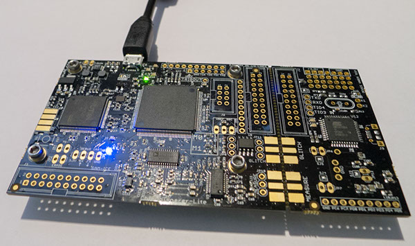
This tutorial uses the CW1173_ChipWhisperer-Lite hardware. No hardware setup is required normally, simply plug in the USB cable:
Note that under no circumstances as part of the setup should you use the CW1173 device to hold up furniture:
=== CW1173 (Lite) Hardware Setup === This tutorial uses the CW1173_ChipWhisperer-Lite hardware. No hardware setup is required normally, simply plug in the USB cable:
Note that under no circumstances as part of the setup should you use the CW1173 device to hold up furniture:
CW1200 (Pro) Hardware Setup
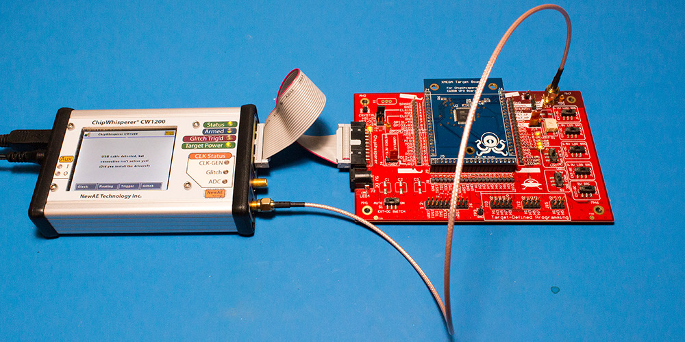
This tutorial uses the CW1200_ChipWhisperer-Pro hardware.
- Remove the ChipWhisperer-Pro main capture hardware, UFO Board, and SMA cable from the ChipWhisperer-Pro case.
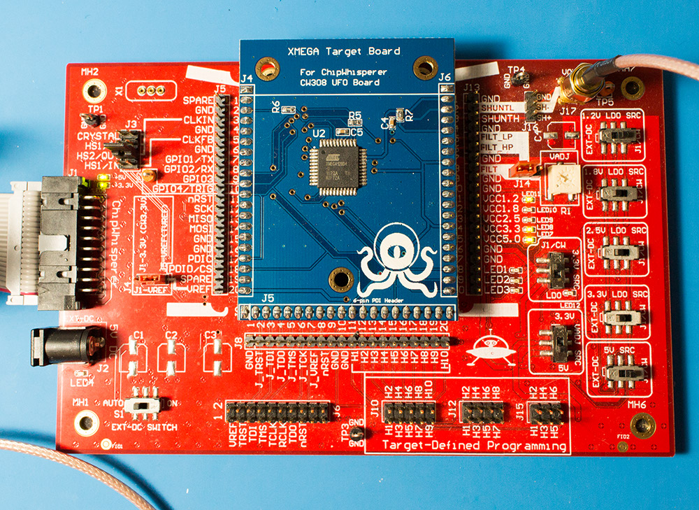
- Attached the UFO board to the ChipWhisperer-Pro with the 20-pin cable, and connect the VOUT SMA connector to the MEASURE input.
- Power up the ChipWhisperer-Pro with the 5V DC power adapter, and connect the USB cable to the computer.
- If this the first time powering up, you will need to install the drivers (see CW1200_ChipWhisperer-Pro).
Note if you have modified the UFO board the jumpers may no longer be at default locations. The jumper settings required are:
- XMEGA Target board mounted
- J3 routes HS2/OUT to CLKIN
- J1 set to "J5-VREF" (right two pins shorted)
- J14 set to "FILT" (left two pins shorted)
- "3.3V SRC" switch set to "J1/CW"
=== CW1200 (Pro) Hardware Setup === This tutorial uses the CW1200_ChipWhisperer-Pro hardware.
- Remove the ChipWhisperer-Pro main capture hardware, UFO Board, and SMA cable from the ChipWhisperer-Pro case.
- Attached the UFO board to the ChipWhisperer-Pro with the 20-pin cable, and connect the VOUT SMA connector to the MEASURE input.
- Power up the ChipWhisperer-Pro with the 5V DC power adapter, and connect the USB cable to the computer.
- If this the first time powering up, you will need to install the drivers (see CW1200_ChipWhisperer-Pro).
Note if you have modified the UFO board the jumpers may no longer be at default locations. The jumper settings required are:
- XMEGA Target board mounted
- J3 routes HS2/OUT to CLKIN
- J1 set to "J5-VREF" (right two pins shorted)
- J14 set to "FILT" (left two pins shorted)
- "3.3V SRC" switch set to "J1/CW"
CW308 (UFO) Hardware Setup
Coming soon!
=== CW308 (UFO) Hardware Setup === Coming soon!
Programming the Target
Programming the XMEGA Target
It is assumed that you've already followed the guide in Installing_ChipWhisperer. Thus it is assumed you are able to communicate with the ChipWhisperer CW1173 hardware (or whatever capture hardware you are using). Note in particular you must have configured the FPGA bitstream in the ChipWhisperer-Capture software, all part of the description in the Installing_ChipWhisperer guide.
Assuming this setup is complete, you can confirm you are able to communicate with the hardware by running the example capture of traces given in the CW1173_ChipWhisperer-Lite quick-start.
Programming the Example
Note with the XMEGA target, you need to configure a clock before programming of the device will succeed. Programming of the target device will be done as part of the CW-Capture software setup, discussed next.
Communicating from CW-Capture Software
Next, open the CW-Capture software. Then perform the following steps:
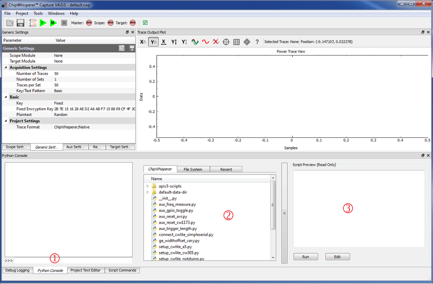
- Switch to the Python Console tab.
- The script selection window (2) lists available example scripts. Scroll down to "connect_cwlite_simpleserial.py" and click on it.
- You will see the script contents appear in the "Script Preview" window (3). You can either hit the "Run" button or double-click the filename of the script to execute it. Do either of those now.
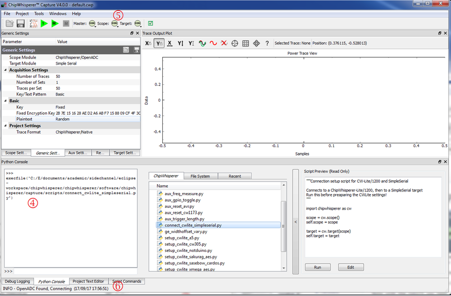
The window should change to indicate the connect succeeded:
- The console lists the exact script that is executed. Note you could have manually executed the script commands line-by-line in this console.
- The "Scope" and "Target" buttons will show as connected.
- The Status Bar will show a connection.
Note in previous software versions, this tutorial took you through manual setup. This can still be done (using the GUI), but instead now the API has been made more powerful, so the example configuration script will be used instead.
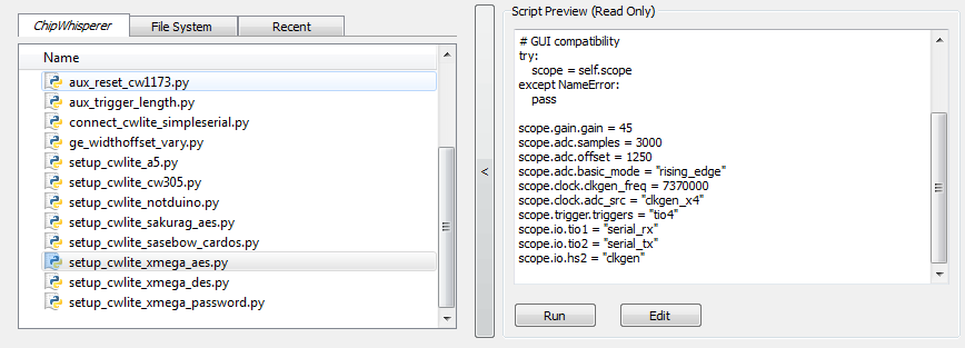
To do so, simply scroll down and select the "setup_cwlite_xmega_aes.py" file:
You'll notice the contents of the script contain the following setup: 1 scope.gain.gain = 45
2 scope.adc.samples = 3000
3 scope.adc.offset = 1250
4 scope.adc.basic_mode = "rising_edge"
5 scope.clock.clkgen_freq = 7370000
6 scope.clock.adc_src = "clkgen_x4"
7 scope.trigger.triggers = "tio4"
8 scope.io.tio1 = "serial_rx"
9 scope.io.tio2 = "serial_tx"
10 scope.io.hs2 = "clkgen"
Line 1: Sets the input ADC gain
Line 2: Sets the number of samples to record as 3000 samples long (this is normally used for the AES algorithm).
Line 3: Sets an offset of 1250 samples from the trigger to when we start recording samples.
Line 4: Sets the trigger as being a "rising edge" trigger.
Line 5: Sets the internal clock generator to 7.37MHz
Line 6: Sets the ADC as running at 4x that clock (so 29.48MHz)
Line 7: Sets the trigger pin as GPIO4 (we previously set the trigger condition as rising edge, so this pin will be the one a rising edge is expected on).
Line 8: Configures GPIO1 as the RX (Input). This is what the XMEGA target expects.
Line 9: Configures GPIO2 as the TX (Output). This is what the XMEGA target expects.
Line 10: Sets the "High-Speed 2" (HS2) pin as having the 7.37MHz clock output.
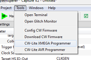
You can now program the XMEGA device! To do so, open the XMEGA Programmer from the Tools menu:
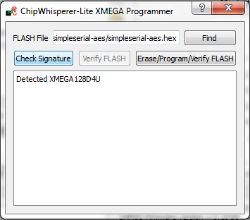
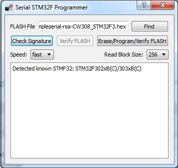
Hit the Check Signature button and confirm the device is detected. If not you may have issues with the clock setup.
Using the Find button, navigate to the
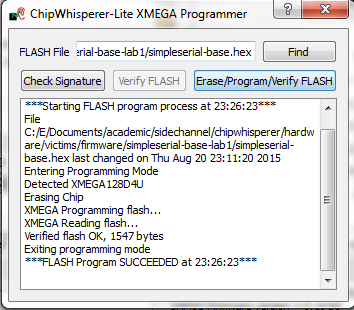
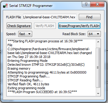
simpleserial-base-cw303.hex(or whatever your hex file is called), which you built earlier with themakecommand. You can then press the Erase/Program/Verify button, and confirm the file is programmed into the XMEGA device:Note the programmer dialog not only shows the successful programming status, but also shows when the
.hexfile was last modified. Always confirm this matches with when you last remember compiling the program -- if it is widely different this suggests you have selected the wrong file!
- You can now close the programming dialog if you'd like. If you're frequently reprogramming the target, you may want to leave this open.
=== Programming the XMEGA Target === It is assumed that you've already followed the guide in Installing_ChipWhisperer. Thus it is assumed you are able to communicate with the ChipWhisperer CW1173 hardware (or whatever capture hardware you are using). Note in particular you must have configured the FPGA bitstream in the ChipWhisperer-Capture software, all part of the description in the Installing_ChipWhisperer guide.
Assuming this setup is complete, you can confirm you are able to communicate with the hardware by running the example capture of traces given in the CW1173_ChipWhisperer-Lite quick-start.
Programming the Example
Note with the XMEGA target, you need to configure a clock before programming of the device will succeed. Programming of the target device will be done as part of the CW-Capture software setup, discussed next.
Communicating from CW-Capture Software
Next, open the CW-Capture software. Then perform the following steps:
- Switch to the Python Console tab.
- The script selection window (2) lists available example scripts. Scroll down to "connect_cwlite_simpleserial.py" and click on it.
- You will see the script contents appear in the "Script Preview" window (3). You can either hit the "Run" button or double-click the filename of the script to execute it. Do either of those now.
The window should change to indicate the connect succeeded:
- The console lists the exact script that is executed. Note you could have manually executed the script commands line-by-line in this console.
- The "Scope" and "Target" buttons will show as connected.
- The Status Bar will show a connection.
Note in previous software versions, this tutorial took you through manual setup. This can still be done (using the GUI), but instead now the API has been made more powerful, so the example configuration script will be used instead.
To do so, simply scroll down and select the "setup_cwlite_xmega_aes.py" file:
You'll notice the contents of the script contain the following setup: 1 scope.gain.gain = 45
2 scope.adc.samples = 3000
3 scope.adc.offset = 1250
4 scope.adc.basic_mode = "rising_edge"
5 scope.clock.clkgen_freq = 7370000
6 scope.clock.adc_src = "clkgen_x4"
7 scope.trigger.triggers = "tio4"
8 scope.io.tio1 = "serial_rx"
9 scope.io.tio2 = "serial_tx"
10 scope.io.hs2 = "clkgen"
Line 1: Sets the input ADC gain
Line 2: Sets the number of samples to record as 3000 samples long (this is normally used for the AES algorithm).
Line 3: Sets an offset of 1250 samples from the trigger to when we start recording samples.
Line 4: Sets the trigger as being a "rising edge" trigger.
Line 5: Sets the internal clock generator to 7.37MHz
Line 6: Sets the ADC as running at 4x that clock (so 29.48MHz)
Line 7: Sets the trigger pin as GPIO4 (we previously set the trigger condition as rising edge, so this pin will be the one a rising edge is expected on).
Line 8: Configures GPIO1 as the RX (Input). This is what the XMEGA target expects.
Line 9: Configures GPIO2 as the TX (Output). This is what the XMEGA target expects.
Line 10: Sets the "High-Speed 2" (HS2) pin as having the 7.37MHz clock output.
You can now program the XMEGA device! To do so, open the XMEGA Programmer from the Tools menu:
Hit the Check Signature button and confirm the device is detected. If not you may have issues with the clock setup.
Using the Find button, navigate to the
simpleserial-base-cw303.hex(or whatever your hex file is called), which you built earlier with themakecommand. You can then press the Erase/Program/Verify button, and confirm the file is programmed into the XMEGA device:Note the programmer dialog not only shows the successful programming status, but also shows when the
.hexfile was last modified. Always confirm this matches with when you last remember compiling the program -- if it is widely different this suggests you have selected the wrong file!
- You can now close the programming dialog if you'd like. If you're frequently reprogramming the target, you may want to leave this open.
Programming the STM32F3 (CW303 Arm) Target
It is assumed that you've already followed the guide in Installing_ChipWhisperer. Thus it is assumed you are able to communicate with the ChipWhisperer CW1173 hardware (or whatever capture hardware you are using). Note in particular you must have configured the FPGA bitstream in the ChipWhisperer-Capture software, all part of the description in the Installing_ChipWhisperer guide.
Assuming this setup is complete, you can confirm you are able to communicate with the hardware by running the example capture of traces given in the CW1173_ChipWhisperer-Lite quick-start.
Programming the Example
Note with the CW303 Arm target, you need to configure a clock before programming of the device will succeed. Programming of the target device will be done as part of the CW-Capture software setup, discussed next.
Communicating from CW-Capture Software
Next, open the CW-Capture software. Then perform the following steps:
- Switch to the Python Console tab.
- The script selection window (2) lists available example scripts. Scroll down to "connect_cwlite_simpleserial.py" and click on it.
- You will see the script contents appear in the "Script Preview" window (3). You can either hit the "Run" button or double-click the filename of the script to execute it. Do either of those now.
The window should change to indicate the connect succeeded:
- The console lists the exact script that is executed. Note you could have manually executed the script commands line-by-line in this console.
- The "Scope" and "Target" buttons will show as connected.
- The Status Bar will show a connection.
Note in previous software versions, this tutorial took you through manual setup. This can still be done (using the GUI), but instead now the API has been made more powerful, so the example configuration script will be used instead.
To do so, simply scroll down and select the "setup_cwlite_stm32f_aes.py" file:
You'll notice the contents of the script contain the following setup: 1 scope.gain.gain = 45
2 scope.adc.samples = 5000
3 scope.adc.offset = 0
4 scope.adc.basic_mode = "rising_edge"
5 scope.clock.clkgen_freq = 7370000
6 scope.clock.adc_src = "clkgen_x4"
7 scope.trigger.triggers = "tio4"
8 scope.io.tio1 = "serial_rx"
9 scope.io.tio2 = "serial_tx"
10 scope.io.hs2 = "clkgen"
11
12 target.baud=38400
Line 1: Sets the input ADC gain
Line 2: Sets the number of samples to record as 5000 samples long (this is normally used for the AES algorithm).
Line 3: Sets an offset of 0 samples from the trigger to when we start recording samples.
Line 4: Sets the trigger as being a "rising edge" trigger.
Line 5: Sets the internal clock generator to 7.37MHz
Line 6: Sets the ADC as running at 4x that clock (so 29.48MHz)
Line 7: Sets the trigger pin as GPIO4 (we previously set the trigger condition as rising edge, so this pin will be the one a rising edge is expected on).
Line 8: Configures GPIO1 as the RX (Input). This is what the ARM target expects.
Line 9: Configures GPIO2 as the TX (Output). This is what the ARM target expects.
Line 10: Sets the "High-Speed 2" (HS2) pin as having the 7.37MHz clock output.
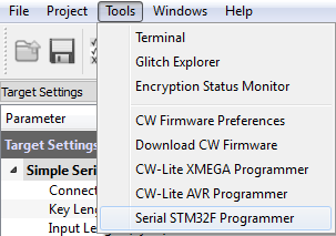
Line 12: Sets the serial communication speed with the target at 38400 baud.You can now program the ARM device! To do so, open the STM32F Programmer from the Tools menu:
Hit the Check Signature button and confirm the device is detected. If not you may have issues with the clock setup.
Using the Find button, navigate to the
simpleserial-base-CWLITEARM.hex(or whatever your binary is called), which you built earlier with themakecommand. You can then press the Erase/Program/Verify button, and confirm the file is programmed into the XMEGA device:If the software freezes and the verification fails after a long period of time, set the Read Block Size to 64 instead of 256.
Note the programmer dialog not only shows the successful programming status, but also shows when the
.hexfile was last modified. Always confirm this matches with when you last remember compiling the program -- if it is widely different this suggests you have selected the wrong file!If you'd like, you can close the STM32F programmer dialog. If you frequently reprogram the target, you may want to leave it open.
=== Programming the STM32F3 (CW303 Arm) Target === It is assumed that you've already followed the guide in Installing_ChipWhisperer. Thus it is assumed you are able to communicate with the ChipWhisperer CW1173 hardware (or whatever capture hardware you are using). Note in particular you must have configured the FPGA bitstream in the ChipWhisperer-Capture software, all part of the description in the Installing_ChipWhisperer guide.
Assuming this setup is complete, you can confirm you are able to communicate with the hardware by running the example capture of traces given in the CW1173_ChipWhisperer-Lite quick-start.
Programming the Example
Note with the CW303 Arm target, you need to configure a clock before programming of the device will succeed. Programming of the target device will be done as part of the CW-Capture software setup, discussed next.
Communicating from CW-Capture Software
Next, open the CW-Capture software. Then perform the following steps:
- Switch to the Python Console tab.
- The script selection window (2) lists available example scripts. Scroll down to "connect_cwlite_simpleserial.py" and click on it.
- You will see the script contents appear in the "Script Preview" window (3). You can either hit the "Run" button or double-click the filename of the script to execute it. Do either of those now.
The window should change to indicate the connect succeeded:
- The console lists the exact script that is executed. Note you could have manually executed the script commands line-by-line in this console.
- The "Scope" and "Target" buttons will show as connected.
- The Status Bar will show a connection.
Note in previous software versions, this tutorial took you through manual setup. This can still be done (using the GUI), but instead now the API has been made more powerful, so the example configuration script will be used instead.
To do so, simply scroll down and select the "setup_cwlite_stm32f_aes.py" file:
You'll notice the contents of the script contain the following setup: 1 scope.gain.gain = 45
2 scope.adc.samples = 5000
3 scope.adc.offset = 0
4 scope.adc.basic_mode = "rising_edge"
5 scope.clock.clkgen_freq = 7370000
6 scope.clock.adc_src = "clkgen_x4"
7 scope.trigger.triggers = "tio4"
8 scope.io.tio1 = "serial_rx"
9 scope.io.tio2 = "serial_tx"
10 scope.io.hs2 = "clkgen"
11
12 target.baud=38400
Line 1: Sets the input ADC gain
Line 2: Sets the number of samples to record as 5000 samples long (this is normally used for the AES algorithm).
Line 3: Sets an offset of 0 samples from the trigger to when we start recording samples.
Line 4: Sets the trigger as being a "rising edge" trigger.
Line 5: Sets the internal clock generator to 7.37MHz
Line 6: Sets the ADC as running at 4x that clock (so 29.48MHz)
Line 7: Sets the trigger pin as GPIO4 (we previously set the trigger condition as rising edge, so this pin will be the one a rising edge is expected on).
Line 8: Configures GPIO1 as the RX (Input). This is what the ARM target expects.
Line 9: Configures GPIO2 as the TX (Output). This is what the ARM target expects.
Line 10: Sets the "High-Speed 2" (HS2) pin as having the 7.37MHz clock output.
Line 12: Sets the serial communication speed with the target at 38400 baud.You can now program the ARM device! To do so, open the STM32F Programmer from the Tools menu:
Hit the Check Signature button and confirm the device is detected. If not you may have issues with the clock setup.
Using the Find button, navigate to the
simpleserial-base-CWLITEARM.hex(or whatever your binary is called), which you built earlier with themakecommand. You can then press the Erase/Program/Verify button, and confirm the file is programmed into the XMEGA device:If the software freezes and the verification fails after a long period of time, set the Read Block Size to 64 instead of 256.
Note the programmer dialog not only shows the successful programming status, but also shows when the
.hexfile was last modified. Always confirm this matches with when you last remember compiling the program -- if it is widely different this suggests you have selected the wrong file!If you'd like, you can close the STM32F programmer dialog. If you frequently reprogram the target, you may want to leave it open.
Programming Other Targets
Programming other targets typically requires additional tools, such as a target specific programmer or debugger. Please see the wiki page for your target for additional details. Additionally, you should run connect_simpleserial.py and the associated setup_*.py script before moving on to the rest of the tutorial.
=== Programming Other Targets === Programming other targets typically requires additional tools, such as a target specific programmer or debugger. Please see the wiki page for your target for additional details. Additionally, you should run connect_simpleserial.py and the associated setup_*.py script before moving on to the rest of the tutorial.
Capturing the Traces
Once the hardware is ready, we can capture some traces for our attack using the ChipWhisperer Capture software. If you somehow got to the 5th Advanced Tutorial without getting this software ready, you can follow the helpful guide at Installing ChipWhisperer.
The first thing we need to do is add a new target to the ChipWhisperer system. (None of the existing ones know about the bootloader's data format, nor do they recognize the CRC responses that are sent back to us.) The code for this target is included in #Appendix A: Target Code. Copy/paste this into a Python file (call it whatever you want) and save it in a place where ChipWhisperer will look for it. There are two folders that you can use:
- Your computer should have a folder called
chipwhisperer_projects- if you don't know where this is, the File > Preferences window will tell you. The system looks in the folderchipwhisperer_projects\chipwhisperer\capture\targetsfor new targets, so you can save your file here. - Alternatively, all of the normal targets are stored in
chipwhisperer\software\chipwhisperer\capture\targets, so you can also save the file here. Note that this may not be possible if you don't have access to these folders (ex: your account doesn't have admin access).
Next is the capture script. In some of the previous tutorials, we entered all of the capture settings by hand. Since we are civilized humans armed with technology, we can use a script to do all of this setup for us. A pre-written Python script is provided at #Appendix B: Capture Script. Take a look at this code and notice what it does:
- it fills in the scope, target, and trace format that we'll use;
- it connects to the hardware; and
- it loads all of the hardware parameters for us. Nice!
Copy this script into a .py file somewhere convenient. Then, perform the following steps to finish the capture:
- Run the capture script, which will open a ChipWhisperer Capture window with everything connected for us.
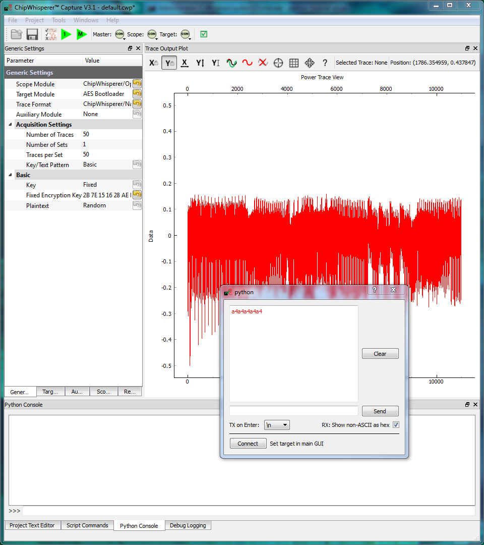
- Open the terminal (Tools > Terminal) and connect to the board. While the terminal is open, press the Capture 1 button. A single byte of data should appear in the terminal. This byte will either be
a1(CRC failed) ora4(CRC OK). If you see any other responses, something is wrong. - Once you're happy with this, open the General Settings tab and set the Number of Traces. You should need around 100 traces to break AES.
- Press the Capture Many button to record the 100 traces. You'll see the new traces plotted on-screen.
- Once the program is finished capturing the traces, save the project. Put it somewhere memorable and give it a nice name.
Finding the Encryption Key
Now that we have our traces, we can go ahead and perform the attack. As described in the background theory, we'll have to do two attacks - one to get the 14th round key, and another (using the first result) to get the 13th round key. Then, we'll do some post-processing to finally get the 256 bit encryption key.
14th Round Key
We can attack the 14th round key with a standard, no-frills CPA attack:
- Open the ChipWhisperer Analyzer program and load the
.cwpfile with the 13th and 14th round traces. This can be either theaes256_round1413_key0_100.cwpfile downloaded or the capture you performed. - View and manipulate the trace data with the following steps:
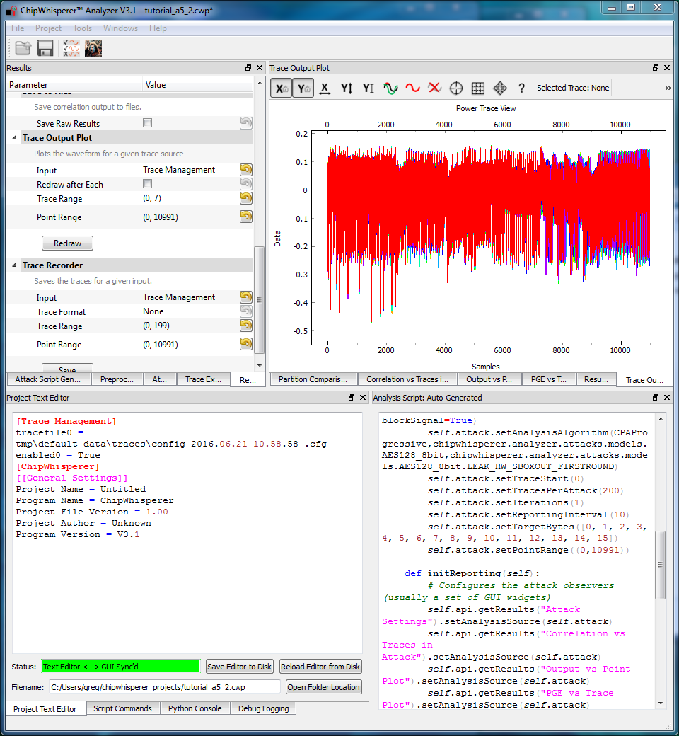
- Switch to the Trace Output Plot tab
- Switch to the Results parameter setting tab
- Choose the traces to be plotted and press the Redraw button to draw them
- Right-click on the waveform to change options, or left-click and drag to zoom
- Use the toolbar to quickly reset the zoom back to original
- Set up the attack in the Attack script:
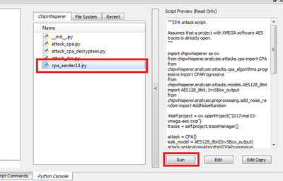
- Make a copy of the attack_cpa.py script, call it something new (such as attack_aesdec14.py)
- Adjust the model from SBox_output to InvSBox_output. This is done by finding the following line in the script:
-
from chipwhisperer.analyzer.attacks.models.AES128_8bit import AES128_8bit, SBox_output
- and change that line to:
-
from chipwhisperer.analyzer.attacks.models.AES128_8bit import AES128_8bit, InvSBox_output
-
- and then also change this further down where we set the leakage model:
-
leak_model = AES128_8bit(InvSBox_output)
-
- If you're finding the attack very slow, narrow down the attack a bit. Normally, this requires a bit of investigation to determine which ranges of the trace are important. Here, you can use the range from 2900 to 4200 for XMEGA and from 1400 to 2600 for STM32F3 (CW303 Arm). The default settings will also work fine, so if you're using another target, you may want to attack the full range. To narrow the attack, edit the
attack.setPointRange(0, -1)with the new range.-
attack.setPointRange((2900, 4200))
-
- Note that we do not know the secret encryption key, so we cannot highlight the correct key automatically. If you want to fix this, the Results settings tab has a Highlighted Key setting. Change this to Override mode and enter the key
ea 79 79 20 c8 71 44 7d 46 62 5f 51 85 c1 3b cb. - Finally, run the attack by switching to the Results Table tab and then hitting the Run button while your script is selected.
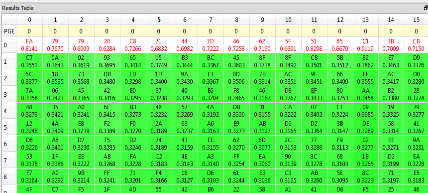
There are a few ways to check the results of the attack. First, the results table will show the best guesses for each subkey. With the highlight override enabled, the red bytes should be the best guesses for every single subkey:
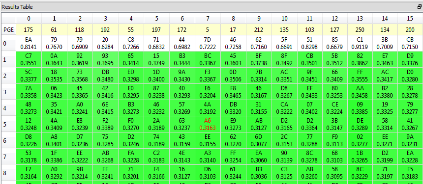
However, the correct key will still rise to the top even if the wrong bytes are highlighted. The coloring and correlation coefficients in the results table should still make it clear that the top guess is the best one:
The default capture stores the WRONG knownkey, so you will have highlighted bytes that are not the correct key. We are looking instead for a large delta between the best-guess and all other guesses. For example for Byte 0 we have the most likely as 0.8141, and 2nd best guess as 0.3551. If our best guess was 0.8141 and 2nd best guess was 0.7981 this would indicate we likely haven't broken the key.
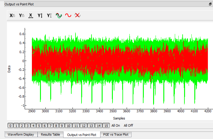
Finally, the Output vs Point Plot shows the correlation against all of the sample points. The spikes on this plot show exactly where the attack was successful (ie: where the sensitive data was leaked):
In any case, we've determined that the correct 14th round key is ea 79 79 20 c8 71 44 7d 46 62 5f 51 85 c1 3b cb.
NOTE: if you're stuck, a full listing of the attack script is given in #Appendix C: AES-256 14th Round Key Script.
13th Round Key
Unfortunately, we cannot use the GUI to attack the 13th round key. The system has no built-in model for round 13 of the AES-256 algorithm. Instead, we can write our own script and insert a custom model into the system. See #Appendix D: AES-256 13th Round Key Script for complete script used here.
Resynchronizing Traces (XMEGA only)
- Open the ChipWhisperer Analyzer software again and reopen the project file (if closed).
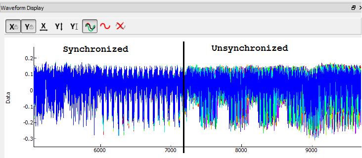
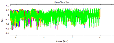
- Recall from the 14th round attack that the trace data becomes unsynchronized around sample 7000. This is due to a non-constant AES implementation: the code does not always take the same amount of time to run for every input. (It's actually possible to do a timing attack on this AES implementation! We'll stick with our CPA attack for now.)
- Resynchronize the traces, see the separate 'Preprocessing' tutorial (NB: only in slides right now!)
Continuing the Attack
The next step is to program our own leakage model. The following Python code models the Hamming weight model of the 13th round S-box:
 python
# Imports for AES256 Attack
from chipwhisperer.analyzer.attacks.models.AES128_8bit import AESLeakageHelper

class AES256_Round13_Model(AESLeakageHelper):
    def leakage(self, pt, ct, guess, bnum):
        #You must but YOUR recovered 14th round key here - this example may not be accurate!
        calc_round_key = [0xea, 0x79, 0x79, 0x20, 0xc8, 0x71, 0x44, 0x7d, 0x46, 0x62, 0x5f, 0x51, 0x85, 0xc1, 0x3b, 0xcb]
        xored = [calc_round_key[i] ^ pt[i] for i in range(0, 16)]
        block = xored
        block = self.inv_shiftrows(block)
        block = self.inv_subbytes(block)
        block = self.inv_mixcolumns(block)
        block = self.inv_shiftrows(block)
        result = block
        return self.inv_sbox((result[bnum] ^ guess[bnum]))
You can look back at the C code of the AES-256 decryption to see how this is implementing the decryption code. Note that because of the Inverse MixColumns operation, we need the entire input ciphertext -- otherwise, we would only need to operate on one byte of the ciphertext.
The last step is to perform the attack using this model:
- Add the above function to your custom script file.
- Change the
setAnalysisAlgorithmin the script to use your custom functions by making the following call:leak_model = AES128_8bit(AES256_Round13_Model)
- As we did in the 14th round attack, reducing the point range can speed up the attack. For example, to use a smaller range of points, try changing the
setPointRange()function call toself.attack.setPointRange((8000,10990))
on XMEGA orself.attack.setPointRange((6500,8500))
for the STM32.
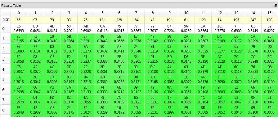
- Start the attack! Wait for the attack to complete, and you will determine the 13th round key:
Note you can check #Appendix C AES-256 13th Round Key Script for the complete contents of the attack script.
Finally, we need to convert this hypothetical key into the actual value of the 13th round key. We can do this by passing the key through ShiftRows and MixColumns to remove the effect of these two functions. This is easy to do in the Python console (assuming we had the recovered key C6 BD 4E 50 AB CA 75 77 79 87 96 CA 1C 7F C5 82, if you recovered a different key replace the knownkey value with yours):
python
>>> from chipwhisperer.analyzer.attacks.models.aes.funcs import shiftrows,mixcolumns
>>> knownkey = [0xC6, 0xBD, 0x4E, 0x50, 0xAB, 0xCA, 0x75, 0x77, 0x79, 0x87, 0x96, 0xCA, 0x1C, 0x7F, 0xC5, 0x82]
>>> key = shiftrows(knownkey)
>>> key = mixcolumns(key)
>>> print " ".join(["%02x" % i for i in key])
c6 6a a6 12 4a ba 4d 04 4a 22 03 54 5b 28 0e 63
Our hard work has rewarded us with the 13th round key, which is c6 6a a6 12 4a ba 4d 04 4a 22 03 54 5b 28 0e 63.
Recovering the Encryption Key
Finally, we have enough information to recover the initial encryption key. In AES-256, the initial key is used in the key expansion routine to generate 15 round keys, and we know the key for round 13 and 14. All we need to do now is reverse the key scheduling algorithm to calculate the 0/1 Round Key from the 13/14 Round Key.
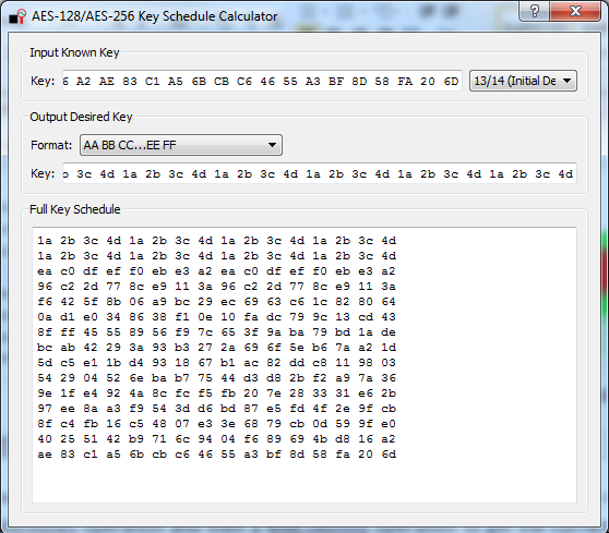
In the ChipWhisperer Analyzer software, a key schedule calculator is provided in Tools > AES Key Schedule:
Open this tool and paste the 13/14 round keys, which are
c6 6a a6 12 4a ba 4d 04 4a 22 03 54 5b 28 0e 63 ea 79 79 20 c8 71 44 7d 46 62 5f 51 85 c1 3b cb
Tell the tool that this key is the 13/14 round key; it will automatically display the entire key schedule and the initial encryption key. You should find the initial encryption key is:
94 28 5d 4d 6d cf ec 08 d8 ac dd f6 be 25 a4 99 c4 d9 d0 1e c3 40 7e d7 d5 28 d4 09 e9 f0 88 a1
Peek into supersecret.h, confirm that this is the right key, and celebrate!
Next Steps
If you want to go further with this tutorial, Tutorial A5-Bonus Breaking AES-256 Bootloader continues working with the same firmware to find the remaining secrets in the bootloader (the IV and the signature).
Appendix A: Target Code
#!/usr/bin/python
# -*- coding: utf-8 -*-
#
# Copyright (c) 2013-2016, NewAE Technology Inc
# All rights reserved.
#
# Authors: Colin O'Flynn, Greg d'Eon
#
# Find this and more at newae.com - this file is part of the chipwhisperer
# project, http://www.assembla.com/spaces/chipwhisperer
#
#    This file is part of chipwhisperer.
#
#    chipwhisperer is free software: you can redistribute it and/or modify
#    it under the terms of the GNU General Public License as published by
#    the Free Software Foundation, either version 3 of the License, or
#    (at your option) any later version.
#
#    chipwhisperer is distributed in the hope that it will be useful,
#    but WITHOUT ANY WARRANTY; without even the implied warranty of
#    MERCHANTABILITY or FITNESS FOR A PARTICULAR PURPOSE.  See the
#    GNU Lesser General Public License for more details.
#
#    You should have received a copy of the GNU General Public License
#    along with chipwhisperer.  If not, see <http://www.gnu.org/licenses/>.
#=================================================

import sys
import time
import chipwhisperer.capture.ui.CWCaptureGUI as cwc
from chipwhisperer.common.api.CWCoreAPI import CWCoreAPI
from chipwhisperer.capture.targets.SimpleSerial import SimpleSerial
from chipwhisperer.common.scripts.base import UserScriptBase
from chipwhisperer.capture.targets._base import TargetTemplate
from chipwhisperer.common.utils import pluginmanager
from chipwhisperer.capture.targets.simpleserial_readers.cwlite import SimpleSerial_ChipWhispererLite
from chipwhisperer.common.utils.parameter import setupSetParam

# Class Crc
#############################################################
# These CRC routines are copy-pasted from pycrc, which are:
# Copyright (c) 2006-2013 Thomas Pircher <tehpeh@gmx.net>
#
class Crc(object):
    """
    A base class for CRC routines.
    """

    def __init__(self, width, poly):
        """The Crc constructor.

        The parameters are as follows:
            width
            poly
            reflect_in
            xor_in
            reflect_out
            xor_out
        """
        self.Width = width
        self.Poly = poly


        self.MSB_Mask = 0x1 << (self.Width - 1)
        self.Mask = ((self.MSB_Mask - 1) << 1) | 1

        self.XorIn = 0x0000
        self.XorOut = 0x0000

        self.DirectInit = self.XorIn
        self.NonDirectInit = self.__get_nondirect_init(self.XorIn)
        if self.Width < 8:
            self.CrcShift = 8 - self.Width
        else:
            self.CrcShift = 0

    def __get_nondirect_init(self, init):
        """
        return the non-direct init if the direct algorithm has been selected.
        """
        crc = init
        for i in range(self.Width):
            bit = crc & 0x01
            if bit:
                crc ^= self.Poly
            crc >>= 1
            if bit:
                crc |= self.MSB_Mask
        return crc & self.Mask


    def bit_by_bit(self, in_data):
        """
        Classic simple and slow CRC implementation.  This function iterates bit
        by bit over the augmented input message and returns the calculated CRC
        value at the end.
        """
        # If the input data is a string, convert to bytes.
        if isinstance(in_data, str):
            in_data = [ord(c) for c in in_data]

        register = self.NonDirectInit
        for octet in in_data:
            for i in range(8):
                topbit = register & self.MSB_Mask
                register = ((register << 1) & self.Mask) | ((octet >> (7 - i)) & 0x01)
                if topbit:
                    register ^= self.Poly

        for i in range(self.Width):
            topbit = register & self.MSB_Mask
            register = ((register << 1) & self.Mask)
            if topbit:
                register ^= self.Poly

        return register ^ self.XorOut


class BootloaderTarget(TargetTemplate):
    _name = 'AES Bootloader'

    def __init__(self):
        TargetTemplate.__init__(self)

        ser_cons = pluginmanager.getPluginsInDictFromPackage("chipwhisperer.capture.targets.simpleserial_readers", True, False)
        self.ser = ser_cons[SimpleSerial_ChipWhispererLite._name]

        self.keylength = 16
        self.input = ""
        self.crc = Crc(width=16, poly=0x1021)
        self.setConnection(self.ser)

    def setKeyLen(self, klen):
        """ Set key length in BITS """
        self.keylength = klen / 8

    def keyLen(self):
        """ Return key length in BYTES """
        return self.keylength

    def getConnection(self):
        return self.ser

    def setConnection(self, con):
        self.ser = con
        self.params.append(self.ser.getParams())
        self.ser.connectStatus.connect(self.connectStatus.emit)
        self.ser.selectionChanged()

    def con(self, scope=None):
        if not scope or not hasattr(scope, "qtadc"): Warning(
            "You need a scope with OpenADC connected to use this Target")

        self.ser.con(scope)
        # 'x' flushes everything & sets system back to idle
        self.ser.write("xxxxxxxxxxxxxxxxxxxxxxxxxxxxxxxxxx")
        self.ser.flush()
        self.connectStatus.setValue(True)

    def close(self):
        if self.ser != None:
            self.ser.close()
        return

    def init(self):
        pass

    def setModeEncrypt(self):
        return

    def setModeDecrypt(self):
        return

    def convertVarToString(self, var):
        if isinstance(var, str):
            return var

        sep = ""
        s = sep.join(["%c" % b for b in var])
        return s

    def loadEncryptionKey(self, key):
        pass

    def loadInput(self, inputtext):
        self.input = inputtext

    def readOutput(self):
        # No actual output
        return [0] * 16

    def isDone(self):
        return True

    def checkEncryptionKey(self, kin):
        return kin

    def go(self):
        # Starting byte is 0x00
        message = [0x00]

        # Append 16 bytes of data
        message.extend(self.input)

        # Append 2 bytes of CRC for input only (not including 0x00)
        crcdata = self.crc.bit_by_bit(self.input)

        message.append(crcdata >> 8)
        message.append(crcdata & 0xff)

        # Write message
        message = self.convertVarToString(message)
        for i in range(0, 5):
            self.ser.flush()
            self.ser.write(message)
            time.sleep(0.1)
            data = self.ser.read(1)

            if len(data) > 0:
                resp = ord(data[0])

                if resp == 0xA4:
                    # Encryption run OK
                    break

                if resp != 0xA1:
                    raise IOError("Bad Response %x" % resp)

        if len(data) > 0:
            if resp != 0xA4:
                raise IOError("Failed to communicate, last response: %x" % resp)
        else:
            raise IOError("Failed to communicate, no response")
Appendix B: Capture Script
Note you need to manually CONNECT to the CW-Lite & AES Bootloader target before running this. To do this:
- Set the 'Scope Module' as 'ChipWhisperer/OpenADC'
- Set the 'Target Module' as 'AES Bootloader' (you need to have that target on your system)
"""Setup script for CWLite/1200 with XMEGA (CW303/CW308-XMEGA/CWLite target)
specifically for Tutorial A5: the AES-256 bootloader attack
"""

try:
    scope = self.scope
except NameError:
    pass

scope.gain.gain = 45
scope.adc.samples = 11000
scope.adc.offset = 0
scope.adc.basic_mode = "rising_edge"
scope.clock.clkgen_freq = 7370000
scope.clock.adc_src = "clkgen_x4"
scope.trigger.triggers = "tio4"
scope.io.tio1 = "serial_rx"
scope.io.tio2 = "serial_tx"
scope.io.hs2 = "clkgen"
Appendix C: AES-256 14th Round Key Script
Full attack script, copy/paste into a file then run from within ChipWhisperer-Analyzer:
import chipwhisperer as cw
from chipwhisperer.analyzer.attacks.cpa import CPA
from chipwhisperer.analyzer.attacks.cpa_algorithms.progressive import CPAProgressive
from chipwhisperer.analyzer.attacks.models.AES128_8bit import AES128_8bit, InvSBox_output

#self.project = cw.openProject("2017-mar23-xmega-aes.cwp")
traces = self.project.traceManager()

attack = CPA()
leak_model = AES128_8bit(InvSBox_output)
attack.setAnalysisAlgorithm(CPAProgressive, leak_model)
attack.setTraceSource(traces)
attack.setTraceStart(0)
attack.setTracesPerAttack(-1)
attack.setIterations(1)
attack.setReportingInterval(10)
attack.setTargetSubkeys([0, 1, 2, 3, 4, 5, 6, 7, 8, 9, 10, 11, 12, 13, 14, 15])
attack.setPointRange((2900, 4200))

self.results_table.setAnalysisSource(attack)
self.correlation_plot.setAnalysisSource(attack)
self.output_plot.setAnalysisSource(attack)
self.pge_plot.setAnalysisSource(attack)
attack.processTraces()
Appendix D: AES-256 13th Round Key Script
import chipwhisperer as cw
from chipwhisperer.analyzer.attacks.cpa import CPA
from chipwhisperer.analyzer.attacks.cpa_algorithms.progressive import CPAProgressive
from chipwhisperer.analyzer.attacks.models.AES128_8bit import AES128_8bit, AESLeakageHelper
from chipwhisperer.analyzer.preprocessing.resync_sad import ResyncSAD

class AES256_Round13_Model(AESLeakageHelper):
    def leakage(self, pt, ct, guess, bnum):
        #You must but YOUR recovered 14th round key here - this example may not be accurate!
        calc_round_key = [0xea, 0x79, 0x79, 0x20, 0xc8, 0x71, 0x44, 0x7d, 0x46, 0x62, 0x5f, 0x51, 0x85, 0xc1, 0x3b, 0xcb]
        xored = [calc_round_key[i] ^ pt[i] for i in range(0, 16)]
        block = xored
        block = self.inv_shiftrows(block)
        block = self.inv_subbytes(block)
        block = self.inv_mixcolumns(block)
        block = self.inv_shiftrows(block)
        result = block
        return self.inv_sbox((result[bnum] ^ guess[bnum]))

traces = self.project.traceManager()

resync_traces = ResyncSAD(traces)
resync_traces.enabled = True
resync_traces.ref_trace = 0
resync_traces.target_window = (9100, 9300)
resync_traces.max_shift = 200

attack = CPA()
leak_model = AES128_8bit(AES256_Round13_Model)
attack.setAnalysisAlgorithm(CPAProgressive, leak_model)
attack.setTraceSource(resync_traces)
attack.setTraceStart(0)
attack.setTracesPerAttack(-1)
attack.setIterations(1)
attack.setReportingInterval(10)
attack.setTargetSubkeys([0, 1, 2, 3, 4, 5, 6, 7, 8, 9, 10, 11, 12, 13, 14, 15])
attack.setPointRange((0, -1))

self.results_table.setAnalysisSource(attack)
self.correlation_plot.setAnalysisSource(attack)
self.output_plot.setAnalysisSource(attack)
self.pge_plot.setAnalysisSource(attack)
attack.processTraces()
