Tutorial A8 32bit AES
Most of our previous tutorials were running on 8-bit modes of operation. We can target typical implementation on ARM devices which actually looks a little different.
This tutorial is ONLY possible if you have an ARM target. For example the UFO Board with the STM32F3 target (or similar).
Background
A 32-bit machine can operate on 32-bit words, so it seems wasteful to use the same 8-bit operations. Indeed we can speed up the AES operation considerably by generating several tables (called T-Tables), as was described in the book The Design of Rijndael which was published by the authors of AES.
In order to take advantage of our 32 bit machine, we can examine a typical round of AES. With the exception of the final round, each round looks like:


We'll leave AddRoundKey the way it is. The other operations are:
![b_{i,j} = \text{sbox}[a_{i,j}]](/images/math/6/4/1/6415df716e9b935fc9c37d16878f0919.png)


Note that the ShiftRows operation  is a cyclic shift and the matrix multiplcation in MixColumns denotes the xtime operation in GF(
 ).
).
It's possible to combine all three of these operations into a single line. We can write 4 bytes of  as the linear combination of four different 4 byte vectors:
![\begin{bmatrix}
d_{0,j} \\
d_{1,j} \\
d_{2,j} \\
d_{3,j}
\end{bmatrix}
=
\begin{bmatrix}
02 \\
01 \\
01 \\
03
\end{bmatrix}
\text{sbox}[a_{0,j+0}]\
\oplus
\begin{bmatrix}
03 \\
02 \\
01 \\
01
\end{bmatrix}
\text{sbox}[a_{1,j+1}]\
\oplus
\begin{bmatrix}
01 \\
03 \\
02 \\
01
\end{bmatrix}
\text{sbox}[a_{2,j+2}]\
\oplus
\begin{bmatrix}
01 \\
01 \\
03 \\
02
\end{bmatrix}
\text{sbox}[a_{3,j+3}]](/images/math/9/4/6/946ab37941e282f2c0c1e8f074c6da47.png)
Now, for each of these four components, we can tabulate the outputs for every possible 8-bit input:
![T_0[a] =
\begin{bmatrix}
02 \times \text{sbox}[a] \\
01 \times \text{sbox}[a] \\
01 \times \text{sbox}[a] \\
03 \times \text{sbox}[a] \\
\end{bmatrix}](/images/math/7/2/b/72bd53a52a3c01e374bb28f30a2106ac.png)
![T_1[a] =
\begin{bmatrix}
03 \times \text{sbox}[a] \\
02 \times \text{sbox}[a] \\
01 \times \text{sbox}[a] \\
01 \times \text{sbox}[a] \\
\end{bmatrix}](/images/math/4/1/5/4155399dd040e8c0f159dfb7feeb24da.png)
![T_2[a] =
\begin{bmatrix}
01 \times \text{sbox}[a] \\
03 \times \text{sbox}[a] \\
02 \times \text{sbox}[a] \\
01 \times \text{sbox}[a] \\
\end{bmatrix}](/images/math/a/8/c/a8c34842b479aa366555d8f53a34f42b.png)
![T_3[a] =
\begin{bmatrix}
01 \times \text{sbox}[a] \\
01 \times \text{sbox}[a] \\
03 \times \text{sbox}[a] \\
02 \times \text{sbox}[a] \\
\end{bmatrix}](/images/math/0/1/4/014c550cfd8618bb1251603b9252e4d3.png)
These tables have 2^8 different 32-bit entries, so together the tables take up 4 kB. Finally, we can quickly compute one round of AES by calculating
![\begin{bmatrix}
d_{0,j} \\
d_{1,j} \\
d_{2,j} \\
d_{3,j}
\end{bmatrix}
=
T_0[a_0,j+0] \oplus
T_1[a_1,j+1] \oplus
T_2[a_2,j+2] \oplus
T_3[a_3,j+3]](/images/math/3/f/f/3ffc3240033886af56e6b329c1a43069.png)
All together, with AddRoundKey at the end, a single round now takes 16 table lookups and 16 32-bit XOR operations. This arrangement is much more efficient than the traditional 8-bit implementation. There are a few more tradeoffs that can be made: for instance, the tables only differ by 8-bit shifts, so it's also possible to store only 1 kB of lookup tables at the expense of a few rotate operations.
Note that T-tables don't have a big effect on AES from a side-channel analysis perspective. The SubBytes output is still buried in the T-tables and the other operations are linear, so it's still possible to attack 32-bit AES using the same 8-bit attack methods.
Building Firmware
You will have to build with the PLATFORM set to one of the ARM targets (such as CW308_STM32F0 for the STM32F0 victim, or CW308_STM32F3 for the STM32F3 victim). If you haven't setup the ARM build environment see the page CW308T-STM32F#Example_Projects. Assuming your build environment is OK, you can build it as follows:
  cd chipwhisperer\hardware\victims\firmware\simpleserial-aes
  make PLATFORM=CW308_STM32F3 CRYPTO_TARGET=MBEDTLS
If this works you should get something like the following:
  Creating Symbol Table: simpleserial-aes-CW308_STM32F3.sym
  arm-none-eabi-nm -n simpleserial-aes-CW308_STM32F3.elf > simpleserial-aes-CW308_
  STM32F3.sym
  Size after:
     text    data     bss     dec     hex filename
     8440    1076   10320   19836    4d7c simpleserial-aes-CW308_STM32F3.elf
     +--------------------------------------------------------
     + Built for platform CW308T: STM32F3 Target
     +--------------------------------------------------------
Hardware Setup
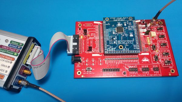
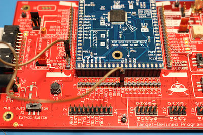
- Using a UFO board, connect your desired STM32Fx target:
- Before finishing the hardware setup, you should connect to the target device. To do this you can use one of the standard setup scripts. This will provide a clock & setup TX/RX lines as expected for the STM32F, which is required for the programmer to work.
Programming STM32F Device
These instructions have been updated for ChipWhisperer 5. If you're using and earlier version, see https://wiki.newae.com/V4:CW308T-STM32F/ChipWhisperer_Bootloader
The STM32Fx devices have a built-in bootloader, and the ChipWhisperer software as of 3.5.2 includes support for this bootloader.
Important notes before we begin:
- You MUST setup a clock and the serial lines for the chip. This is easily done by connecting to the scope and target, then running
default_setup():
import chipwhisperer as cw
scope = cw.scope
target = cw.target(scope)
scope.default_setup()
- On the STM32F1, you MUST adjust the clock frequency to 8MHz. The bootloader does not work with our usual 7.37 MHz clock frequency. This 8MHz frequency does not apply to the code that you're running on the device. Once you're done programming, you'll need to set the frequency back to F_CPU (likely 7.37MHz) For example:
scope.default_setup()
scope.clock.clkgen_freq = 8E6
#program target...
scope.clock.clkgen_freq = 7.37E6
#reset and run as usual
To access the bootloader you can perform these steps. They vary based on if you have a "Rev 02" board or a "Rev 03 or Later" board. The revision number is printed on the bottom side as part of the PCB part number (STM32F-03 is Rev -03 for example).
Rev -03 or Later
Run the following python code once you have the scope and target set up:
prog = cw.programmers.STM32FProgrammer
cw.program_target(scope, prog, "<path to fw hex file>")
If you get errors during the programming process:
- Retry the programming process with a lower baud rate:
prog = cw.programmers.STM32FProgrammer
cw.program_target(scope, prog, "<path to fw hex file>", baud=38400)
- If using a CW308 based STM, try mounting a jumper between the "SH-" and "SH+" pins at J16 (to the left of the SMA connector) on the UFO board. Retry programming with the jumper mounted.
Rev -02 Boards
The Rev -02 boards did not have all programming connections present. They require some additional steps:
- Setup the device as usual:
scope = cw.scope()
target = cw.target(scope)
scope.default_setup()
- Mount a jumper between the H1 and PDIC pins (again this is ONLY for the -02 rev).
- Reset the ARM device either by pressing the reset button (newer UFO boards only), or by toggling power:
import time
scope.io.target_pwr = False
time.sleep(1)
scope.io.target_pwr = True
- Program the device:
prog = cw.programmers.STM32FProgrammer
cw.program_target(scope, prog, "<path to fw hex file>")
- The device should program, it may take a moment to fully program/verify on larger devices.
- Remove the jumper between the H1/H2 pins.
- Reset the ARM device either by pressing the reset button (newer UFO boards only), or by toggling power:
import time
scope.io.target_pwr = False
time.sleep(1)
scope.io.target_pwr = True
Capturing Traces
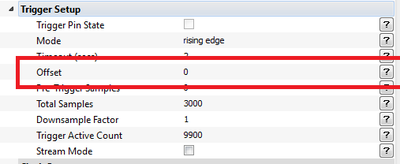
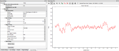
The capture process is similar to previous setups. After running the setup script, adjust the following settings:
Running Attack
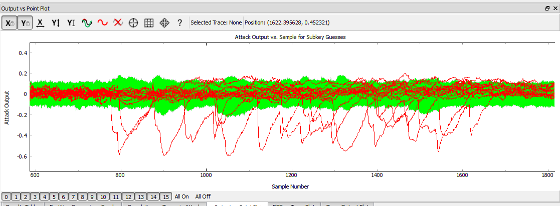
The attach is ran in the same manner as previous AES attacks, we use the same leakage assumptions as we don't actually care about the T-Table implementation. The resulting output vs. point location will look a little "messier", as shown here:
