| As of August 2020 the site you are on (wiki.newae.com) is deprecated, and content is now at rtfm.newae.com. |
Tutorial A2 Introduction to Glitch Attacks (including Glitch Explorer)
This tutorial has been updated for ChipWhisperer 4.0.0 release. If you are using 3.x.x see the "V3" link in the sidebar.
| A2: Introduction to Glitch Attacks (including Glitch Explorer) | |
|---|---|
| Target Architecture | XMEGA |
| Hardware Crypto | No |
| Software Release | V3 / V4 / V5 |
This advanced tutorial will demonstrate clock glitch attacks using the ChipWhisperer system. This will introduce you to many required features of the ChipWhisperer system when it comes to glitching. This will be built on in later tutorials to generate voltage glitching attacks, or when you wish to attack other targets.
Contents
Background on Clock Glitching
Digital hardware devices almost always expect some form of reliable clock. We can manipulate the clock being presented to the device to cause unintended behaviour. We'll be concentrating on microcontrollers here, however other digital devices (e.g. hardware encryption accelerators) can also have faults injected using this technique.
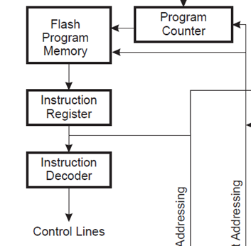
Consider a microcontroller first. The following figure is an excerpt the Atmel AVR ATMega328P datasheet:
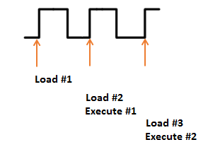
Rather than loading each instruction from FLASH and performing the entire execution, the system has a pipeline to speed up the execution process. This means that an instruction is being decoded while the next one is being retrieved, as the following diagram shows:
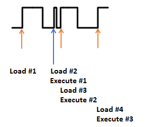
But if we modify the clock, we could have a situation where the system doesn't have enough time to actually perform an instruction. Consider the following, where Execute #1 is effectively skipped. Before the system has time to actually execute it another clock edge comes, causing the microcontroller to start execution of the next instruction:
This causes the microcontroller to skip an instruction. Such attacks can be immensely powerful in practice. Consider for example the following code from `linux-util-2.24`:
/*
 *   auth.c -- PAM authorization code, common between chsh and chfn
 *   (c) 2012 by Cody Maloney <cmaloney@theoreticalchaos.com>
 *
 *   this program is free software.  you can redistribute it and
 *   modify it under the terms of the gnu general public license.
 *   there is no warranty.
 *
 */

#include "auth.h"
#include "pamfail.h"

int auth_pam(const char *service_name, uid_t uid, const char *username)
{
    if (uid != 0) {
        pam_handle_t *pamh = NULL;
        struct pam_conv conv = { misc_conv, NULL };
        int retcode;

        retcode = pam_start(service_name, username, &conv, &pamh);
        if (pam_fail_check(pamh, retcode))
            return FALSE;

        retcode = pam_authenticate(pamh, 0);
        if (pam_fail_check(pamh, retcode))
            return FALSE;

        retcode = pam_acct_mgmt(pamh, 0);
        if (retcode == PAM_NEW_AUTHTOK_REQD)
            retcode =
                pam_chauthtok(pamh, PAM_CHANGE_EXPIRED_AUTHTOK);
        if (pam_fail_check(pamh, retcode))
            return FALSE;

        retcode = pam_setcred(pamh, 0);
        if (pam_fail_check(pamh, retcode))
            return FALSE;

        pam_end(pamh, 0);
        /* no need to establish a session; this isn't a
         * session-oriented activity...  */
    }
    return TRUE;
}
This is the login code for the Linux OS. Note that if we could skip the check of if (uid != 0) and simply branch to the end, we could avoid having to enter a password. This is the power of glitch attacks - not that we are breaking encryption, but simply bypassing the entire authentication module!
Glitch Hardware
The ChipWhisperer Glitch system uses the same synchronous methodology as it's Side Channel Analysis (SCA) capture. A system clock (which can come from either the ChipWhisperer or the Device Under Test (DUT)) is used to generate the glitches. These glitches are then inserted back into the clock, although it's possible to use the glitches alone for other purposes (i.e. for voltage glitching, EM glitching).
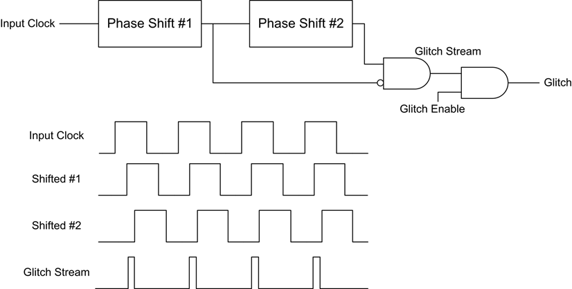
The generation of glitches is done with two variable phase shift modules, configured as follows:
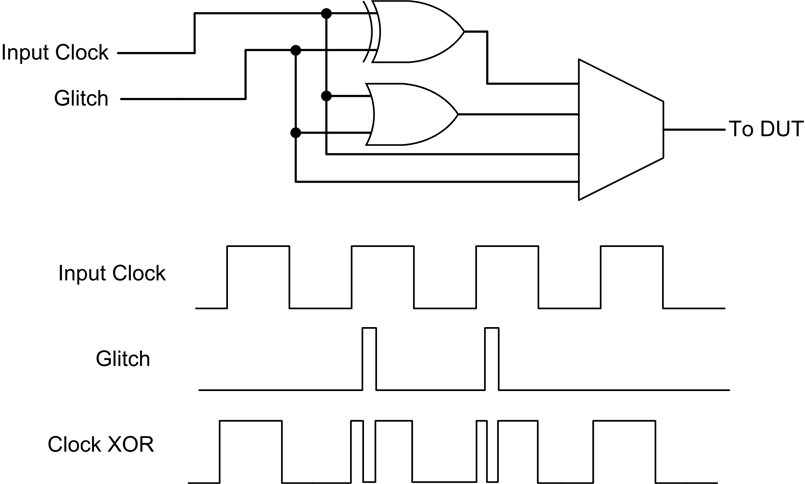
The enable line is used to determine when glitches are inserted. Glitches can be inserted continuously (useful for development) or triggered by some event. The following figure shows how the glitch can be muxd to output to the Device Under Test (DUT).
Hardware Support
The phase shift blocks use the Digital Clock Manager (DCM) blocks within the FPGA. These blocks have limited support for run-time configuration of parameters such as phase delay and frequency generation, and for maximum performance the configuration must be fixed at design time. The Xilinx-provided run-time adjustment can shift the phase only by about +/- 5nS in 30pS increments (exact values vary with operating conditions).
For most operating conditions this is insufficient - if attacking a target at 7.37MHz the clock cycle would have a period of 136nS. In order to provide a larger adjustment range, an advanced FPGA feature called Partial Reconfiguration (PR) is used. The PR system requires special partial bitstreams which contain modifications to the FPGA bitstream. These are stored as two files inside a "firmware" zip which contains both the FPGA bitstream along with a file called glitchwidth.p and a file called glitchoffset.p. If a lone bitstream is being loaded into the FPGA (i.e. not from the zip-file), the partial reconfiguration system is disabled, as loading incorrect partial reconfiguration files could damage the FPGA. This damage is mostly theoretical, more likely the FPGA will fail to function correctly.
If in the course of following this tutorial you find the FPGA appears to stop responding (i.e. certain features no longer work correctly), it could be the partial reconfiguration data is incorrect.
Python GUI Interface
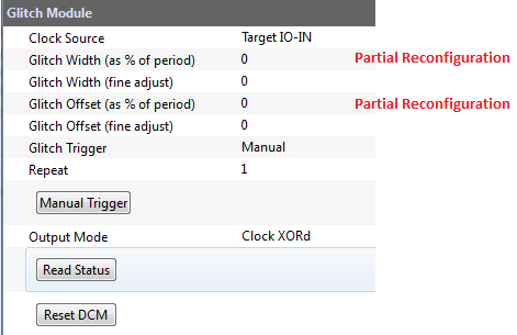
The portion of the GUI of interest to us is primarily located in this section:
If the Partial Reconfiguration system has been disabled (due to missing PR files or files differing from the FPGA bitstream) the two fields marked that say (as % of period) will be disabled. Only the fields labeled (fine adjust) will be available.
Setting up Glitch Example
Firmware Setup
The glitch examples requires you to program the target device. The software to program is located at chipwhisperer\hardware\victims\firmware\glitch-simple of your ChipWhisperer release or GIT clone. As before, open the Makefile and be sure to uncomment the appropriate target to reflect your hardware:
#Multi-Target Board, AVR Device (ATMega328P)
#PLATFORM = CW301_AVR

#CW-Lite XMEGA Target Device (XMEGA128D4)
PLATFORM = CW303
You can build the software by running the make command as follows:
make
You should also open the file glitchsimple.c which is the source code. The subroutine being glitched in this example looks like this:
void glitch_infinite(void)
{
    char str[64];
    //Declared volatile to avoid optimizing away loop.
    //This also adds lots of SRAM access
    volatile uint16_t i, j;
    volatile uint32_t cnt;
    while(1){
        cnt = 0;
        for(i=0; i<500; i++){
            for(j=0; j<500; j++){
                cnt++;
            }
        }
        sprintf(str, "%lu %d %d\n", cnt, i, j);
        uart_puts(str);
    }
}
You should confirm that glitch_infinite() is actually called from the main subroutine. There are several glitch examples and it's possible the wrong subroutine has been setup previously:
int main(void){

    platform_init();
    init_uart();
    trigger_setup();

    /* Uncomment this to get a HELLO message for debug */
    putch('h');
    putch('e');
    putch('l');
    putch('l');
    putch('o');
    putch('\n');
    _delay_ms(20);


    while(1){
        glitch_infinite();
    }

    return 1;
}
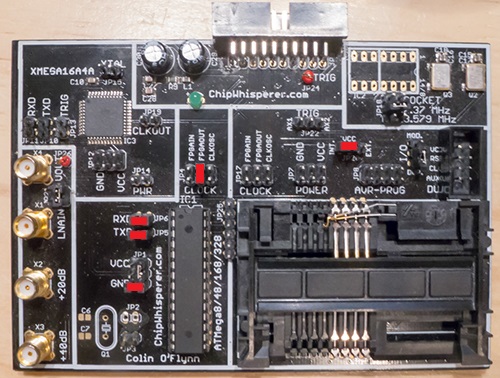
Once the AVR/XMEGA is programmed (see previous tutorials), you may need to setup a few jumpers depending on your hardware.
Hardware Setup
XMEGA Target (CW1173 + CW303)
The XMEGA target on the ChipWhisperer-Lite requires no configuration. If you have separated the boards, you can attach them with the 20-pin cable.
Software Setup
Connect to the ChipWhisperer device:
- As the Scope Module, select the ChipWhisperer/OpenADC option
- As the Target Module, select the Simple Serial option
- Switch to the Scope Settings tab, and as the connection, select the NewAE USB (CWLite/CW1200) or Serial Port (LX9) option
- Switch to the Target Settings tab, and as the connection, select the NewAE USB (CWLite/CW1200) or Serial Port (LX9) option
- Run connect on both the Scope & Target. They should both switch to green circles indicating the system is connected.
Setup the CLKGEN Module to Generate a 7.37 MHz clock and route it through the Glitch Generator
- Switch the Freq Counter Src to the CLKGEN Output
- Set the Desired Frequency to 7.37 MHz. Note you should only adjust the 'frequency' portion of this, if you highlight the entire field you may not be able to type the frequency into the system.
- Confirm the DCM Locked checkbox is checked, if not hit the Reset CLKGEN DCM box. Check the Freq Counter to ensure the system is correctly generating a 7.37 MHz clock.
Under the Glitch Module set the Clock Source as CLKGEN:
Under the Target HS IO-Out option select the Glitch Module:
Connect the Serial Port
- For the XMEGA Target (including the CW-Lite integrated target), perform the following:
- Switch to the Scope Settings tab, and scroll down to Target IOn Pins
- Switch the Target IO1 to be Serial RXD
- Switch the Target IO2 to be Serial TXD
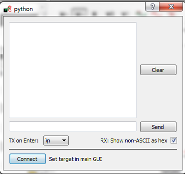
From the Tools menu select Open Terminal, and press Connect on the terminal:
- The baud rate for this system is 38400, which should be the default for the ChipWhisperer serial port.
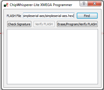
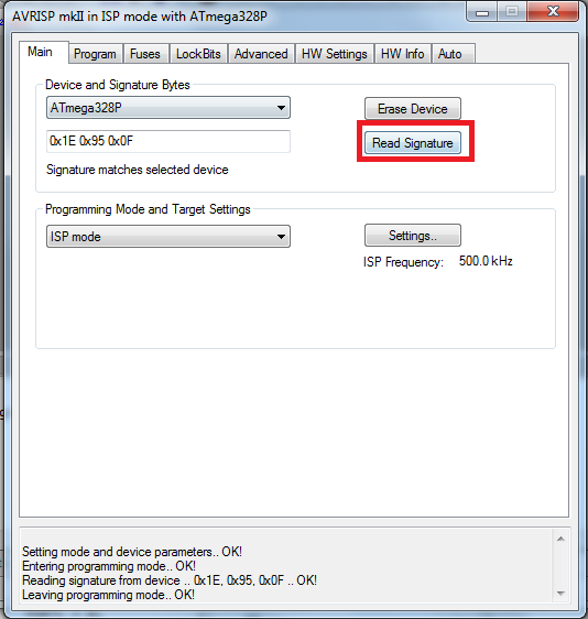
Using the target programmer window, we will use the Read Signature or Check Signature button to reset the target every time we want to restart the program. Confirm this works by pressing the Read Signature button, for example if using the ChipWhisperer-Lite integrated programmer, you would see this window:
But if using the external AVR Studio programmer for the ChipWhisperer Capture Rev2, you would see this window:
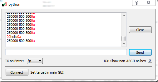
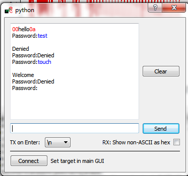
When you press this button the AVR will display the Hello message, which should look something like this:
tip
If you uncheck the RX: Show non-ASCII as hex you will not see the red text with ASCII values of newline (
0a).hint
Sometimes the "reset" message won't appear. This happens often on the virtual machine version, or if your host computer is slow or loaded. Generally you can ignore this error, for example in the video version the welcome message is never printed. You will just have to trust the system is resetting correctly.
- For the XMEGA Target (including the CW-Lite integrated target), perform the following:
We'll now look at glitching this routine. You should inspect the source code to determine that a simple series of calculations are performed:
void glitch_infinite(void)
{
    char str[64];
    //Declared volatile to avoid optimizing away loop.
    //This also adds lots of SRAM access
    volatile uint16_t i, j;
    volatile uint32_t cnt;
    while(1){
        cnt = 0;
        for(i=0; i<500; i++){
            for(j=0; j<500; j++){
                cnt++;
            }
        }
        sprintf(str, "%lu %d %d\n", cnt, i, j);
        uart_puts(str);
    }
}
If the routine works as expected, we would expect it to print 250000 500 500. If a glitch interrupts the program flow, we would expect some of those values to be incorrect. This could be because a loop was skipped, an addition done incorrectly, or the program flow was exited unexpectedly.
Manual Glitch Trigger
To begin with, you'll simply use the manual glitch triggering. This works well in the examples where we have a simple loop we are breaking out of. Doing so requires modifying the glitch width and glitch offset experimentally. The exact values will vary for every device and setup.
It is recommended to only use the glitch width (as % of period) option, as the fine adjust is too small of a change for this lower-speed example. Other hardware may need the precision added by the fine adjust however!
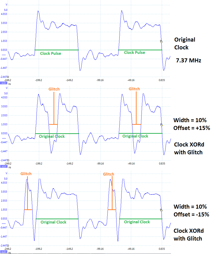
The following figure shows several different settings for a 7.37 MHz clock. The width is set to 10%, which for the 136nS clock period of the 7.37 MHz clock means the glitch width is about 13.6 nS. When the offset is negative, the glitch is placed in-front of the clock. The glitch is XORd with the clock, meaning this becomes a small positive-going glitch in-front of the regular clock pulse.
If the offset is positive, the glitch occurs after the rising edge of the clock pulse. Because this glitch pulse is XORd with the clock, it becomes a negative-going glitch inserted in the 'middle' of the regular clock pulse.
With some background, let's now check some glitches. Assuming you've setup the example as before, do the following:
Adjust the settings for Glitch Width (as % of period) , Glitch Offset (as % of period), and Repeat based on your target and the following table for different targets:
Parameter AVR on Multi-Target (CW301) CW-Lite XMEGA Board Glitch Width (as % of period) 7.5 9.5 Glitch Offset (as % of period) -10 -2 Repeat 5 105 - Ensure Glitch Trigger is Manual
- Hit the Manual Trigger button
- See if you end up with either the target resetting (reprints
hello\n), or if the loop count becomes wrong. You may need to press the Manual Trigger button several times quickly. The objective is to have an incorrect loop count, meaning you caused a glitch! - To force a reset of the target, use the Signature Read option on the programmer.
- Adjust the glith width & offset as needed.
- You may also adjust the Repeat option, or cause it to glitch several instructions.
Be aware that you may crash the target! In the previous examples the target could have reset after each glitch. It may simply go into another infinite loop however, or even enter invalid states. Again force a hardware reset of the target in these cases. It may appear like the target was never glitched, whereas in reality it was glitched into some invalid state.
The boards are extremely sensitive to the glitch width and offset. You may have trouble finding settings that cause a glitch. Don't get too hung up on this; the following sections provide a more reliable method of glitching a target by determining the appropriate parameter settings.
Automatically Resetting Target
If we are going to start with the target at a pre-determined state, we need to reset the target. There are two ways of automatically performing this. The method used here will use the existing programmer interface to reset the device by performing that "read signature" operation we have already been using. The other method is to toggle a GPIO pin, which is more generic for future use.
This was introduced in Tutorial_B3-1_Timing_Analysis_with_Power_for_Password_Bypass#Reset_via_Auxiliary_Module.
To setup the automatic reset, perform the following:
- Scroll down the list of scripts, and you'll find one labeled "aux_reset_cw1173.py". This script has a simple function of attempting to reset the XMEGA device using the programmer:
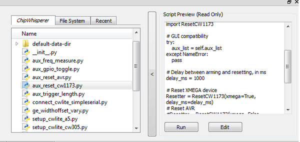
- Hit the "Run" button. If you switch to the "Auxilary Module" tab, you'll see it's been added to the list of modules at the specified location.:
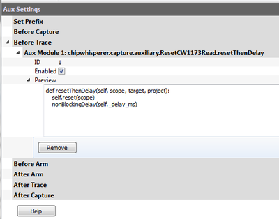
- Looking at the code of the script, you can see how this script is using an external module & linking it to a specific auxilary module trigger:
from chipwhisperer.capture.auxiliary.ResetCW1173Read import ResetCW1173

# GUI compatibility
try:
    aux_list = self.aux_list
except NameError:
    pass

# Delay between arming and resetting, in ms
delay_ms = 1000

# Reset XMEGA device
Resetter = ResetCW1173(xmega=True, delay_ms=delay_ms)
# Reset AVR
#Resetter = ResetCW1173(xmega=False, delay_ms=delay_ms)

# Reset before arming - more stable
aux_list.register(Resetter.resetThenDelay, "before_trace")
# Reset after arming - scope can catch entire reset
#aux_list.register(Resetter.delayThenReset, "after_arm")
- You can edit the values required such as reset time & location by changing the script (using an external editor). But an easier method is to insert it into our attack script itself. As a test we'll see if the default values work. We will later integrate this into a full example script.
We can now confirm the reset works with the "Capture 1" button. This requires us to disable the normal routing of the output data to a file for analysis, as we want to just dump data to the terminal emulator. To do this:
- Switch to the Target Settings tab.
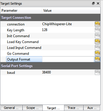
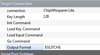
Remove all of the Load Key Command, Go Command, and Output Format options:
- Press the "Capture 1" button a few times, which should confirm on each "capture" the target device is resetting.
Finally, we will switch the glitch target to give us a more realistic target to glitch. To do this open the file
chipwhisperer\hardware\victims\firmware\glitch-simple\glitchsimple.cand modify the call inmain(), such that we now call theglitch1()function. This means the following:while(1){ glitch_infinite(); }can be changed to:
while(1){
    glitch1();
}
After which recompile (with
make), and reprogram the target device. Note the new function being glitched looks like this:void glitch1(void) { led_ok(1); led_error(0); //Some fake variable volatile uint8_t a = 0; putch('A'); //External trigger logic trigger_high(); trigger_low(); //Should be an infinite loop while(a != 2){ ; } led_error(1); led_error(1); led_error(1); led_error(1); led_error(1); led_error(1); led_error(1); led_error(1); led_error(1); uart_puts("1234"); led_error(1); led_error(1); led_error(1); led_error(1); led_error(1); led_error(1); led_error(1); led_error(1); //Several loops in order to try and prevent restarting while(1){ ; } while(1){ ; } while(1){ ; } while(1){ ; } while(1){ ; } }When you perform a Capture 1, the terminal should print
hello\nA, based on the above source code. Note the objective will be to glitch past the infinite loop, such that1234is printed. If using the XMEGA target board this will also turn on the RED led.hint
If the startup message isn't visible, it may be related to issues with the Capture software not being fast enough after reset to display the serial port contents on the terminal emulator. This happens often on the virtual machine environment, as can be seen in the demo video. You can ignore this error for now.
Automatically Triggering Glitch
The manual trigger used previously is suitable when the embedded system is waiting for further input. For example if the embedded system is waiting for a password, you could insert glitches without requiring accurate timing. We'll explore the use of the capture trigger for glitching here, which also improves the repeatability of your glitch attempts.
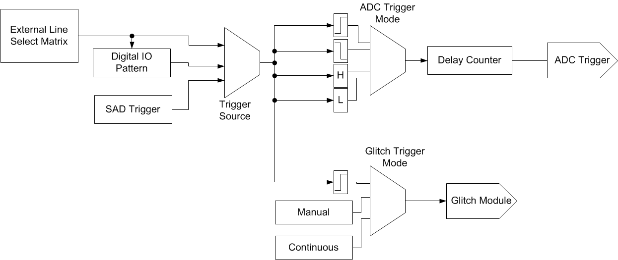
To use this system, you must first understand the routing of the trigger to the glitch module. The following figure shows the trigger routing, which is more basic than the power capture trigger:
Note in particular that if using an external IO pin, you only have a rising edge trigger. The example glitch program includes a line which is set 'High' at critical moments, allowing you to experiment with this basic IO trigger.
Based on the source code loaded, we currently have a trigger to time the glitch. This is very useful during the characterization phase, where we wish to determine what sort of glitch affects this specific hardware. Once we know that, we can move onto glitching a more "realistic" routine.
Before doing that, we will actually enable the power analysis capture. To do this:
- Switch to the Scope Settings tab.
- Switch the ADC Clock Source as being CLKGEN x4.
- Press Reset ADC DCM, confirm the frequency is 29.5 MHz as expected.
- Switch the Trigger Setup --> Mode to be Rising Edge
- Switch the Trigger Setup --> Total Samples to be 1000
- Switch the Gain Setting --> Setting to be 40. You might need to adjust this for different hardware.
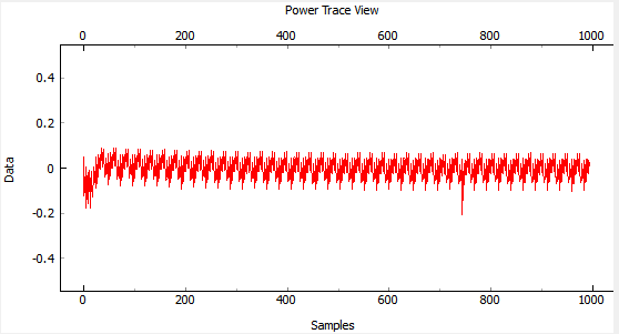
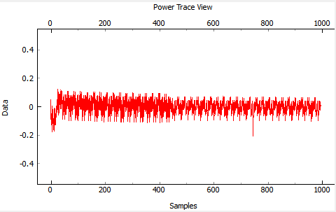
Press Capture 1, confirm some waveform is displayed. For example with the XMEGA Target on the ChipWhisperer-Lite, the waveform looks like this:
- If this does't work: check the trigger in use is the Target IO4 pin.
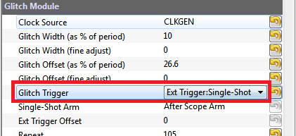
Finally, we can enable the trigger of the glitch to occur based on this external trigger pin. This can be accomplished by:
Switch the Glitch Trigger mode to Ext Trigger:Single-Shot:
Performing a Capture 1, you'll notice that the waveform is now perturbed. This is due to the clock glitches causing odd power consumption behavior:
- Play around a bit with the glitch width, offset, and repeat. You should see different effects in the power consumption traces.
Using the Glitch Explorer
Now that we can automatically perform the glitching, we can use the glitch explorer to automatically vary glitch parameters while recording what the target device is doing. Before continuing with the tutorial, we'll go through an overview of the the glitch explorer.
Glitch Explorer
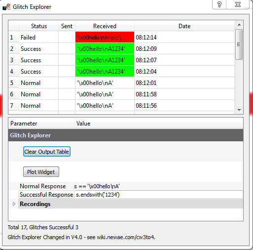
We'll first introduce the Glitch Monitor ("Glitch Explorer") before we go ahead and show you how to use it. The main window of the glitch explorer looks like this:
Where you can see the following parts
- The top part is the output of the system combined with the parameters of the glitch is displayed (the 'output window').
- In the bottom part you can adjust general parameters of the glitching system, such as what counts as a successful glitch or not.
We'll be looking at each of these sections in more detail next.
The Output Window
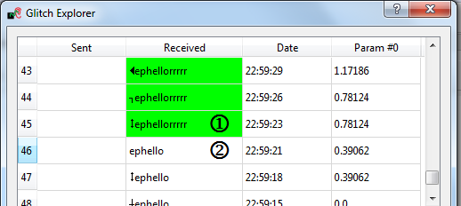
The output window highlights different types of output. In this example we have an output |1| highlighted in green, which is flagged as a successful glitch. This example code was waiting for the rrrr sequence.
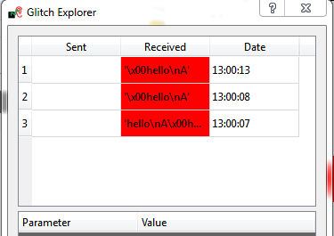
Glitches can also be flagged as 'normal', in which case there is no highlight as in |2|. Finally the glitch could be flagged as an error, in which case it will be highlighted in red.
In order for the glitch explorer to receive the output value, you must insert the special code $GLITCH$ into the Target Settings --> Output Format settings. Data is still sent to the terminal emulator so you can monitor what is happening, but if you don't set the $GLITCH$ special string you won't see it in glitch explorer.
The Main Settings
Details of the main settings:
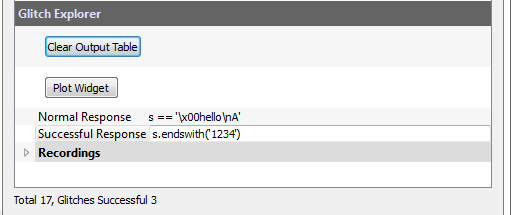
The response of the system during normal operation is set at Normal response. This defines what happens when no glitching or unexpected behavior happened.
The desired response of the system if the glitch was successful is set at Successful response.
The expected and desired responses are expected to be Python expressions, where s is a str-type variable which contains the response of the system. The expression must evaulate to True or False. For example, the following shows examples of what you could use as possible expressions:
| Desired Behavior | Parameter Expression |
|---|---|
| Check for "hello\n" exactly. | s == "hello\n" |
| Check for "hello\n" at end of string. | s.endswith("hello\n") |
| Check for hex 0xAF in last byte position. | ord(s[-1]) == 0xAF |
Note that there is sometimes garbage in the first position. This occurs because if the target device is being reset before the glitch, you may see the serial lines floating. These floating lines may cause invalid characters to be recorded.
Parameter Settings
The actual parameters to change are set via a simple Python script. You will register this script to an appropriate section in the system using the "auxiliary module". Using a script makes it easy to define all sorts of various settings you might find of interest.
For example the following script would insert code to cycle through width and offset settings:
class IterateGlitchWidthOffset(object):
    def __init__(self, ge_window):
        self._starting_offset = -40
        self._starting_width = 5
        self.ge_window = ge_window

    def reset_glitch_to_default(self, scope, target, project):
        """ Set glitch settings to defaults. """
        self.offset = self._starting_offset
        self.width = self._starting_width

    def change_glitch_parameters(self, scope, target, project):
        """ Example of simple glitch parameter modification function. """
        # This value is minimum clock offset/width increment
        self.offset += 0.390625

        if self.offset > 40:
            self.offset = self._starting_offset
            self.width += 0.390625

        if self.width > 40:
            self.width = self._starting_width

        # Write data to scope
        scope.glitch.width = self.width
        scope.glitch.offset = self.offset

        #You MUST tell the glitch explorer about the updated settings
        if self.ge_window:
            self.ge_window.add_data("Glitch Width", scope.glitch.width)
            self.ge_window.add_data("Glitch Offset",scope.glitch.offset)

glitch_iterator = IterateGlitchWidthOffset(self.glitch_explorer)
self.aux_list.register(glitch_iterator.change_glitch_parameters, "before_trace")
self.aux_list.register(glitch_iterator.reset_glitch_to_default, "before_capture")
Note you can quickly cause very long captures to occur! To run the glitch explorer, you need to set the appropriate number of traces on the General Settings tab, and use the Capture Multi to run the glitch explorer.
The ChipWhisperer system has no idea how many iterations are required with your code - it still uses a fixed number of captures by default. Later versions of the API will support an exit signal.
Example Running the Glitch Explorer
This example will attempt to break out the loop in glitch1(). Moving ahead from where you were in #Automatically Triggering Glitch, we will see how we can view the output of the target device in the glitch explorer.
Switch to the Target Settings tab, and set the Output Format to be
$GLITCH$:- From the Tools menu select Glitch Monitor to open the glitch explorer.
Press the Capture 1 button a few times, and you should see the table populated with outputs:
We want to mark them as "normal" or "glitch successful" to get the color-coding working appropriately.
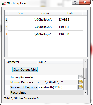
- Double-click on a normal response, and copy the text. In the Normal Response field, we need to compare the magic variable
swith that copied text. Do this by setting the Normal Response to be:s == '\x00hello\nA'. - We want to mark a string ending with
1234as a pass. Thus in the Successful Response field, set the test to bes.endswith('1234')(remember in Python both'and"are valid for string start/end characters). Press Capture 1 a few more times, and check the color-coding has changed:
The next step is to tune the glitch offset to attempt to get a successful clock glitch. These steps are listed as follows:
- Change the Tuning Parameters to be 1.
Set the following in Parameter 0 options:
Option Value Name Offset Parameter Path ['Glitch Module', 'Glitch Offset (as % of period)'] Data Format Float Range -30 : 30 Value -30 Step 0.5 Repeat 1 The Parameter Path option can be found by manually making an adjustment to the Glitch Offset (as % of period) in the GUI, and observing the string printed to the Script Commands tab. The numeric value of the command is not included in the parameter path (i.e., do not copy the value).
On the main GUI in the Scope Settings tab, change the following values for the Glitch Module:
- Repeat set to 10.
- Glitch Width (as % of period) set to 8.0.
These values will be used during the glitch explorer run. We have not specified anything for the tuning, so they will not be changed from whatever is already in the GUI.
On the General Settings tab:
- Ensure the Trace Format is set to None (i.e., no traces will be written to disk).
- Set the Number of Traces to 121.
- Press the Capture Multi button. You will get a warning as there is no trace writer, but can just hit Continue Anyway, since we do not want to store traces to disk.
With any luck, at least one of the glitches will be successful:
If you get a reset (prints 'hello' again), you might need to reduce the "repeat" value. If you have no successful glitches, double-check all settings. You can continue to the next step anyway, as in that step we will also tune the "glitch width".
We may also need to tune the "Glitch Width". We can use knowledge of the successful glitch from the previous step to reduce our search space. In this case, assume we had a successful glitch with a width of 8.0 and offset of 17.5. We'll search around those values to see if we can achieve a more successful glitch performance.
To continue the tutorial, the following steps will be taken:
- In the Glitch Explorer, set the Tuning Parameters to 2.
Configure the second parameter with the following:
Option Value Name Width Parameter Path ['Glitch Module', 'Glitch Width (as % of period)'] Data Format Float Range 5 : 15 Value 5 Step 0.5 Repeat 1 - Change the Range of the first parameter Glitch Offset to span from 1 to 25, since it appeared that negative offsets were never successful in our previous attempts. Be sure to reset the Value of this parameter to your desired starting point (probably 1). This will reduce the search time.
- On the main GUI in the Scope Settings tab, adjust the Glitch Module repeat parameter to be 1. We are now attempting to acheive success with a single clock cycle being glitched.
- Still in the main GUI, adjust the number of traces per capture to be 1000. This reflects the number of iterations required to run through both loops (20 x 50).
- Hit the Capture Multi button and cross your fingers! Hopefully you will see a successful glitch for some combination of glitch width and offset. We aren't quite done yet, as you will also need to do some fine-tuning to achieve high reliability on the glitch.
Record some of the useful parameters by scrolling through the window (WARNING: changing parameters will clear the table, so record useful values now). In this example there was a success at Offset = 8.5%, and Width = 7.5%. Let's see how to fine-tune those values:
- Plug those values into the main GUI Glitch Module setting. If we use the Capture 1 button values are taken from the main GUI, instead of the glitch explorer.
- Press the Capture 1 button a few times. You'll note it records the output of the device, which may not be generating successful glitches (NB: the "offset" and "width" recorded in the table may be wrong when using the Capture 1 button, as the glitch explorer is not recording values from the main GUI correctly. This is a bug in the display only, the correct values are being sent to the device).
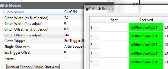
Using arrow keys, nudge the Glitch Offset (fine adjust) up and down. Try performing a Capture 1 to see if you are able to achieve a reliable glitch. In this example setting the fine adjust to 44 resulted in a very reliable glitch:
You might want to try seeing if there is an upper limit to this setting, and putting it mid-way between the lower and upper limits for generating a glitch.
Congrats! You've now performed some tuning to achieve a reliable glitch on the target device. The next step is to glitch something more fun - like a password check.
Glitching a Password Check
This assumes you now have a set of parameters which caused a reliable glitch. We'll now glitch past a password check, initially using our trigger as a crutch. The function of interest compares a received password to some known password. The glitch3() function looks as follows:
void glitch3(void)
{
    char inp[16];
    char c = 'A';
    unsigned char cnt = 0;
    uart_puts("Password:");

    while((c != '\n') & (cnt < 16)){
        c = getch();
        inp[cnt] = c;
        cnt++;
    }

    char passwd[] = "touch";
    char passok = 1;

    trigger_high();
    trigger_low();

    //Simple test - doesn't check for too-long password!
    for(cnt = 0; cnt < 5; cnt++){
        if (inp[cnt] != passwd[cnt]){
            passok = 0;
        }
    }

    if (!passok){
        uart_puts("Denied\n");
    } else {
        uart_puts("Welcome\n");
    }
}
The following assumes you have already completed the previous steps:
- Close the glitch explorer.
- Modify the file
glitchexample.cto callglitch3()instead ofglitch1(), which is to say simply change the main function called frommain()toglitch3(). - Run
makein the folderchipwhisperer\hardware\victims\firmware\glitch-simple. - Program the target device with your
.hexfile. - On the Target Settings tab, clear the Output Format field. That is remove the
$GLITCH$text, as we are no longer using the glitch explorer. If you don't do this, you will not see any output of the device on the terminal emulator. - Open the terminal emulator, and connect to it again (if you closed it).
Reset the device, it should prompt you for a password. The correct password is
touch, try both correct and incorrect passwords. The program as designed loops after a password try to prompt you again. You should see both correct and incorrect responses:- On the Scope Settings tab, adjust the Timeout(s) to a larger value such as 20. We need a longer timeout to work with the serial terminal.
Let's try a glitch insertion! Perform the following:
- Press the Capture 1 button. This will reset the target and arm the glitch.
- Before the timeout, enter a wrong password such as
testin the terminal and hit enter. - See if you can get the wrong password accepted. If not, let's use the Glitch Explorer to automate the parameter adjustments.
Switching to the Auxiliary Settings tab, adjust the delay on the reset such that you have a 150 mS delay. This will mean once the device resets there is a delay while it prints the startup message.
Switch to the Target Settings tab:
- In the Go Command field, put the bad password such as
test\n. - In the Output Format field, put
$GLITCH$to route the output to the glitch explorer.
- In the Go Command field, put the bad password such as
- Open the Glitch Explorer, and press Capture 1. You should see the Denied message come across.
In the Glitch Explorer, adjust the following settings:
- Set Tuning Parameters to 1
Set Parameter 0 options to:
Option Value Name Trigger Offset Parameter Path ['Glitch Module', 'Ext Trigger Offset'] Data Format Int Range 0 : 200 Value 0 Step 1 Repeat 1
- Set the number of traces on the General Settings tab to 200.
- On the main GUI, in the Scope Settings tab, ensure that you have the number of repeats on the Glitch Module set to 1. We will start with a single clock cycle glitched.
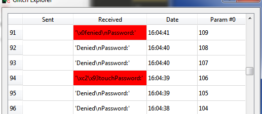
Press Capture Multi. Monitor the glitch outputs, you may see some errors or a successful glitch. Note that sometimes the errors are useful - here is an example where the glitched code actually dumped the password:
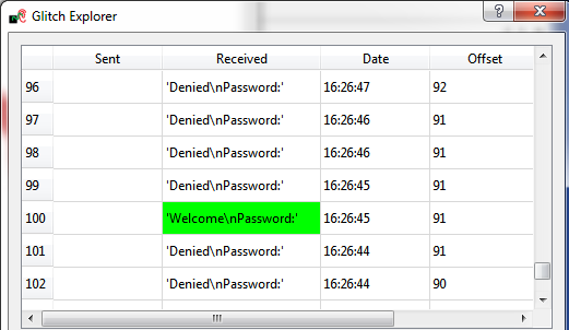
More likely you might see a "Welcome" message indicating the password check was glitched:
If the previous step isn't successful, increase the "repeat" count on the Glitch Module section of the Scope Settings tab, and try again. In this example I actually needed a repeat count of "3" to get the successful "Welcome" message printed above.
You can also increase the repeat count in the glitch explorer, which simply tries the same settings multiple times. You will likely find that the successful glitch does not have 100% success rate, so using a repeat count of 2 or 3 is helpful to increase your chances of success.
Glitching Onward
This basic tutorial has introduced you to glitch attacks. They are a powerful tool for bypassing authentication in embedded hardware devices. There are many ways to expand your knowledge with additional practice, such as:
- Use manual glitches to try simply glitching past the prompt in
glitch3(). - Download some example source code (bootloaders, login prompts, etc) and port them to the AVR. See how you can glitch past security checks.
- Use one of the IO triggers discussed in Tutorial_A1_Synchronization_to_Communication_Lines.
