| As of August 2020 the site you are on (wiki.newae.com) is deprecated, and content is now at rtfm.newae.com. |
V4:Tutorial B1 Building a SimpleSerial Project
This tutorial has been updated for ChipWhisperer 4.0.0 release. If you are using 3.x.x see the "V3" link in the sidebar.
| B1: Building a SimpleSerial Project | |
|---|---|
| Target Architecture | XMEGA/ARM/Other |
| Hardware Crypto | No |
| Software Release | V3 / V4 / V5 |
This tutorial will introduce you to the 'simpleserial' communications system. It will show you how to perform different operations on data based on input from the ChipWhisperer software. This can be used for building your own system which you wish to 'break'.
For users of the ChipWhisperer Lite with ARM target, you'll want to ensure you have the latest updates to the ChipWhisperer platform. This can be done by using the ChipWhisperer Git Update program, or by using git to checkout the develop branch and pulling any updates.
Contents
What is SimpleSerial
SimpleSerial is the communications protocol used for almost all of the ChipWhisperer demo project. It's a very basic serial protocol which can be easily implemented on most systems. This system communicates using a standard asynchronous serial protocol, 38400 baud, 8-N-1.
All messages are sent in ASCII-text, and are normally terminated with a line-feed ('\n'). This allows you to interact with the simpleserial system over a standard terminal emulator.
The following message types are defined:
-
x - Sending a 'x' resets the buffers. This does not require a line-feed termination. It is suggested to always send a stream of x's to initilize the system in case the device was already in some other mode due to noise/corruption.
-
k00112233445566778899AABBCCDDEEFF\\n - Loads the encryption key
00112233445566778899AABBCCDDEEFFinto the system. If not called the system may use some default key. -
pAABBCCDDEEFF00112233445566778899\\n - Encrypts the data
AABBCCDDEEFF00112233445566778899with the key loaded with the 'k' command. The system will respond with a string starting with r, as shown next. -
rCBBD4A2B34F2571758FF6A797E09859D\\n - This is the response from the system. If data has been encrypted with a 'p' for example, the system will respond with the 'r' sequence automatically. So sending the earlier example means the result of the encryption was
cbbd4a2b34f2571758ff6a797e09859d.
Building the Basic Example
For this example, we'll be working off ofsimpleserial-base firmware, which by default just echos the 16 bytes we send to the target back to us.
Building for CWLite with XMEGA Target
You'll need to have installed avr-gcc and avr-libc. You may have already done this by following the installation guide, or if using the ChipWhisperer-VM it comes prepared with avr-gcc already setup. See the Installing_ChipWhisperer guide for details.
Once you have a working compiler (check by typing 'avr-gcc' at the command line - if using Windows you may need to setup a special batch file to provide you with a avr-gcc command prompt).
- We want to use the existing SimpleSerial firmware as a base for our project, but we don't want to edit the existing firmware. Instead, we'll make a new project with a copy of this firmware. Copy the directory of the firmware you want to modify in the
chipwhisperer/hardware/vicitims/firmwareto a new folder. The folder you copy will depend on what tutorial you're doing. Typically, the firmware you want to use is listed above the "Building for ..." drop down menus in this wiki. The name is arbitrary, but for this example, we'll call itsimpleserial-LAB-SPECIFIC-FOLDER(though depending on what firmware and tutorial you're working off of, you may want to call it something different). You must keep it in the same directory, as it will reference other files within that directory for the build process. - Open a terminal with avr-gcc in the path. If using Windows the sidebar on the Installing_ChipWhisperer page - you can either add WinAVR to your system path, or you can run the 'winavr.bat' file suggested.
Change the terminal to the newly copied directory. For example:
Windows:cd c:\chipwhisperer\hardware\victims\firmware\simpleserial-LAB-SPECIFIC-FOLDER
Linux/macOS:cd chipwhisperer/hardware/victims/firmware/simpleserial-LAB-SPECIFIC-FOLDER
Then, run
maketo build the system. Make sure you specify which platform you're using as your target. For example, for the ChipWhisperer Lite target, runmake PLATFORM=CW303
Which should have the following output:
...Bunch of lines removed...
Creating Extended Listing: simpleserial-base.lss
avr-objdump -h -S -z simpleserial-base.elf > simpleserial-base.lss

Creating Symbol Table: simpleserial-base.sym
avr-nm -n simpleserial-base.elf > simpleserial-base.sym

Size after:
AVR Memory Usage
----------------
Device: atxmega128d3

Program:    1524 bytes (1.1% Full)
(.text + .data + .bootloader)

Data:        224 bytes (2.7% Full)
(.data + .bss + .noinit)


Built for platform CW-Lite XMEGA

-------- end --------
Ensure that the "Built for platform ___" matches your target device.
=== Building for CWLite with XMEGA Target === You'll need to have installed avr-gcc and avr-libc. You may have already done this by following the installation guide, or if using the ChipWhisperer-VM it comes prepared with avr-gcc already setup. See the Installing_ChipWhisperer guide for details.
Once you have a working compiler (check by typing 'avr-gcc' at the command line - if using Windows you may need to setup a special batch file to provide you with a avr-gcc command prompt).
- We want to use the existing SimpleSerial firmware as a base for our project, but we don't want to edit the existing firmware. Instead, we'll make a new project with a copy of this firmware. Copy the directory of the firmware you want to modify in the
chipwhisperer/hardware/vicitims/firmwareto a new folder. The folder you copy will depend on what tutorial you're doing. Typically, the firmware you want to use is listed above the "Building for ..." drop down menus in this wiki. The name is arbitrary, but for this example, we'll call itsimpleserial-LAB-SPECIFIC-FOLDER(though depending on what firmware and tutorial you're working off of, you may want to call it something different). You must keep it in the same directory, as it will reference other files within that directory for the build process. - Open a terminal with avr-gcc in the path. If using Windows the sidebar on the Installing_ChipWhisperer page - you can either add WinAVR to your system path, or you can run the 'winavr.bat' file suggested.
Change the terminal to the newly copied directory. For example:
Windows:cd c:\chipwhisperer\hardware\victims\firmware\simpleserial-LAB-SPECIFIC-FOLDER
Linux/macOS:cd chipwhisperer/hardware/victims/firmware/simpleserial-LAB-SPECIFIC-FOLDER
Then, run
maketo build the system. Make sure you specify which platform you're using as your target. For example, for the ChipWhisperer Lite target, runmake PLATFORM=CW303
Which should have the following output:
...Bunch of lines removed...
Creating Extended Listing: simpleserial-base.lss
avr-objdump -h -S -z simpleserial-base.elf > simpleserial-base.lss

Creating Symbol Table: simpleserial-base.sym
avr-nm -n simpleserial-base.elf > simpleserial-base.sym

Size after:
AVR Memory Usage
----------------
Device: atxmega128d3

Program:    1524 bytes (1.1% Full)
(.text + .data + .bootloader)

Data:        224 bytes (2.7% Full)
(.data + .bss + .noinit)


Built for platform CW-Lite XMEGA

-------- end --------
Ensure that the "Built for platform ___" matches your target device.
Building for CWLite with Arm Target
You'll need to have installed the GNU Embedded Toolchain for ARM. If you haven't yet, see the Installing_ChipWhisperer guide, specifically the Installing ARM Toolchain section, for details.
Once you have a working compiler (check by typing 'arm-none-eabi-gcc' at the command line).
- We want to use the existing SimpleSerial firmware as a base for our project, but we don't want to edit the existing firmware. Instead, we'll make a new project with a copy of this firmware. Copy the directory of the firmware you want to modify in the
chipwhisperer/hardware/vicitims/firmwareto a new folder. The folder you copy will depend on what tutorial you're doing. Typically, the firmware you want to use is listed above the "Building for ..." drop down menus in this tutorial. The name is arbitrary, but for this example, we'll call itsimpleserial-LAB-SPECIFIC-FOLDER(though depending on what firmware and tutorial you're working off of, you may want to call it something different). You must keep it in the same directory, as it will reference other files within that directory for the build process. - Open a terminal with arm-none-eabi-gcc in the path. If using Windows the sidebar on the Installing_ChipWhisperer page
Change the terminal to the newly copied directory. For example:
Windows:cd c:\chipwhisperer\hardware\victims\firmware\simpleserial-LAB-SPECIFIC-FOLDER
Linux/macOS:cd chipwhisperer/hardware/victims/firmware/simpleserial-LAB-SPECIFIC-FOLDER
Then, run
maketo build the system. Make sure you specify which platform you're using as your target. For example, for the ChipWhisperer Lite target, runmake PLATFORM=CWLITEARM CRYPTO_TARGET=TINYAES128C
Which should have the following output:
...Bunch of lines removed...
Linking: simpleserial-base-CWLITEARM.elf
arm-none-eabi-gcc -mcpu=cortex-m4 -I. -mthumb -mfloat-abi=hard -mfpu=fpv4-sp-d16 -fmessage-length=0 -ffunction-sections -gdwarf-2 -DSS_VER=SS_VER_1_1 -DSTM32F303xC -DSTM32F3 -DSTM32 -DDEBUG -DHAL_TYPE=HAL_stm32f3 -DPLATFORM=CWLITEARM -DTINYAES128C -DF_CPU=7372800UL -Os -funsigned-char -funsigned-bitfields -fshort-enums -Wall -Wstrict-prototypes -Wa,-adhlns=objdir/simpleserial-base.o -I.././simpleserial/ -I.././hal -I.././hal/stm32f3 -I.././hal/stm32f3/CMSIS -I.././hal/stm32f3/CMSIS/core -I.././hal/stm32f3/CMSIS/device -I.././hal/stm32f4/Legacy -I.././crypto/ -I.././crypto/tiny-AES128-C -std=gnu99 -MMD -MP -MF .dep/simpleserial-base-CWLITEARM.elf.d objdir/simpleserial-base.o objdir/simpleserial.o objdir/stm32f3_hal.o objdir/stm32f3_hal_lowlevel.o objdir/stm32f3_sysmem.o objdir/aes.o objdir/aes-independant.o objdir/stm32f3_startup.o --output simpleserial-base-CWLITEARM.elf --specs=nano.specs -T .././hal/stm32f3/LinkerScript.ld -Wl,--gc-sections -lm -Wl,-Map=simpleserial-base-CWLITEARM.map,--cref   -lm
.
Creating load file for Flash: simpleserial-base-CWLITEARM.hex
arm-none-eabi-objcopy -O ihex -R .eeprom -R .fuse -R .lock -R .signature simpleserial-base-CWLITEARM.elf simpleserial-base-CWLITEARM.hex
.
Creating load file for EEPROM: simpleserial-base-CWLITEARM.eep
arm-none-eabi-objcopy -j .eeprom --set-section-flags=.eeprom="alloc,load" \
        --change-section-lma .eeprom=0 --no-change-warnings -O ihex simpleserial-base-CWLITEARM.elf simpleserial-base-CWLITEARM.eep || exit 0
.
Creating Extended Listing: simpleserial-base-CWLITEARM.lss
arm-none-eabi-objdump -h -S -z simpleserial-base-CWLITEARM.elf > simpleserial-base-CWLITEARM.lss
.
Creating Symbol Table: simpleserial-base-CWLITEARM.sym
arm-none-eabi-nm -n simpleserial-base-CWLITEARM.elf > simpleserial-base-CWLITEARM.sym
Size after:
   text    data     bss     dec     hex filename
   4588       8    1296    5892    1704 simpleserial-base-CWLITEARM.elf
+--------------------------------------------------------
+ Built for platform CW-Lite Arm (STM32F3)
+--------------------------------------------------------
Ensure that the "Built for platform ___" matches your target device.
=== Building for CWLite with Arm Target === You'll need to have installed the GNU Embedded Toolchain for ARM. If you haven't yet, see the Installing_ChipWhisperer guide, specifically the Installing ARM Toolchain section, for details.
Once you have a working compiler (check by typing 'arm-none-eabi-gcc' at the command line).
- We want to use the existing SimpleSerial firmware as a base for our project, but we don't want to edit the existing firmware. Instead, we'll make a new project with a copy of this firmware. Copy the directory of the firmware you want to modify in the
chipwhisperer/hardware/vicitims/firmwareto a new folder. The folder you copy will depend on what tutorial you're doing. Typically, the firmware you want to use is listed above the "Building for ..." drop down menus in this tutorial. The name is arbitrary, but for this example, we'll call itsimpleserial-LAB-SPECIFIC-FOLDER(though depending on what firmware and tutorial you're working off of, you may want to call it something different). You must keep it in the same directory, as it will reference other files within that directory for the build process. - Open a terminal with arm-none-eabi-gcc in the path. If using Windows the sidebar on the Installing_ChipWhisperer page
Change the terminal to the newly copied directory. For example:
Windows:cd c:\chipwhisperer\hardware\victims\firmware\simpleserial-LAB-SPECIFIC-FOLDER
Linux/macOS:cd chipwhisperer/hardware/victims/firmware/simpleserial-LAB-SPECIFIC-FOLDER
Then, run
maketo build the system. Make sure you specify which platform you're using as your target. For example, for the ChipWhisperer Lite target, runmake PLATFORM=CWLITEARM CRYPTO_TARGET=TINYAES128C
Which should have the following output:
...Bunch of lines removed...
Linking: simpleserial-base-CWLITEARM.elf
arm-none-eabi-gcc -mcpu=cortex-m4 -I. -mthumb -mfloat-abi=hard -mfpu=fpv4-sp-d16 -fmessage-length=0 -ffunction-sections -gdwarf-2 -DSS_VER=SS_VER_1_1 -DSTM32F303xC -DSTM32F3 -DSTM32 -DDEBUG -DHAL_TYPE=HAL_stm32f3 -DPLATFORM=CWLITEARM -DTINYAES128C -DF_CPU=7372800UL -Os -funsigned-char -funsigned-bitfields -fshort-enums -Wall -Wstrict-prototypes -Wa,-adhlns=objdir/simpleserial-base.o -I.././simpleserial/ -I.././hal -I.././hal/stm32f3 -I.././hal/stm32f3/CMSIS -I.././hal/stm32f3/CMSIS/core -I.././hal/stm32f3/CMSIS/device -I.././hal/stm32f4/Legacy -I.././crypto/ -I.././crypto/tiny-AES128-C -std=gnu99 -MMD -MP -MF .dep/simpleserial-base-CWLITEARM.elf.d objdir/simpleserial-base.o objdir/simpleserial.o objdir/stm32f3_hal.o objdir/stm32f3_hal_lowlevel.o objdir/stm32f3_sysmem.o objdir/aes.o objdir/aes-independant.o objdir/stm32f3_startup.o --output simpleserial-base-CWLITEARM.elf --specs=nano.specs -T .././hal/stm32f3/LinkerScript.ld -Wl,--gc-sections -lm -Wl,-Map=simpleserial-base-CWLITEARM.map,--cref   -lm
.
Creating load file for Flash: simpleserial-base-CWLITEARM.hex
arm-none-eabi-objcopy -O ihex -R .eeprom -R .fuse -R .lock -R .signature simpleserial-base-CWLITEARM.elf simpleserial-base-CWLITEARM.hex
.
Creating load file for EEPROM: simpleserial-base-CWLITEARM.eep
arm-none-eabi-objcopy -j .eeprom --set-section-flags=.eeprom="alloc,load" \
        --change-section-lma .eeprom=0 --no-change-warnings -O ihex simpleserial-base-CWLITEARM.elf simpleserial-base-CWLITEARM.eep || exit 0
.
Creating Extended Listing: simpleserial-base-CWLITEARM.lss
arm-none-eabi-objdump -h -S -z simpleserial-base-CWLITEARM.elf > simpleserial-base-CWLITEARM.lss
.
Creating Symbol Table: simpleserial-base-CWLITEARM.sym
arm-none-eabi-nm -n simpleserial-base-CWLITEARM.elf > simpleserial-base-CWLITEARM.sym
Size after:
   text    data     bss     dec     hex filename
   4588       8    1296    5892    1704 simpleserial-base-CWLITEARM.elf
+--------------------------------------------------------
+ Built for platform CW-Lite Arm (STM32F3)
+--------------------------------------------------------
Ensure that the "Built for platform ___" matches your target device.
Building for Other Targets
Building for other targets typically requires additional programs and tools. Additionally, some targets may have a unique build process, meaning the instructions here will not apply to them. Please see the page for the specific target you want to build for before following these instructions, which can be found under the Hardware Documentation section of the Main Page.
Once you have a working compiler:
- We want to use the existing SimpleSerial firmware as a base for our project, but we don't want to edit the existing firmware. Instead, we'll make a new project with a copy of this firmware. Copy the directory of the firmware you want to modify in the
chipwhisperer/hardware/vicitims/firmwareto a new folder. The folder you copy will depend on what tutorial you're doing. Typically, the firmware you want to use is listed above the "Building for ..." drop down menus. The name is arbitrary, but for this example, we'll call itsimpleserial-base-lab1(though depending on what firmware and tutorial you're working off of, you may want to call it something different). You must keep it in the same directory, as it will reference other files within that directory for the build process. Change the terminal to the newly copied directory. For example:
Windows:cd c:\chipwhisperer\hardware\victims\firmware\simpleserial-base-lab1
Linux/macOS:cd chipwhisperer/hardware/victims/firmware/simpleserial-base-lab1
Then, run
maketo build the system. Make sure you specify which platform you're using as your target. You can see a list of supported targets by typingmake PLATFORM=. You'll also need to specify aCRYPTO_TARGET. Most targets and tutorials work withTINYAES128C, so if you're unsure, this is usually a reliable option. For example, for the NXP Kinetis K24F target, run:make PLATFORM=CW308_K24F CRYPTO_TARGET=TINYAES128C
Which should have the following output:
...Bunch of lines removed...
Linking: simpleserial-base-CW308_K24F.elf
arm-none-eabi-gcc  -I. -O0 -g -DDEBUG -DCPU_MK24FN1M0VLL12 -DFRDM_K64F -DFREEDOM -w -fno-common -ffunction-sections -fdata-sections -ffreestanding -fno-builtin  -mthumb -mapcs -std=gnu99 -mcpu=cortex-m4 -mfloat-abi=hard -mfpu=fpv4-sp-d16 -MMD -MP -static  -gdwarf-2 -DSS_VER=SS_VER_1_1 -DHAL_TYPE=HAL_k24f -DPLATFORM=CW308_K24F -DTINYAES128C -DF_CPU=7372800UL -Os -funsigned-char -funsigned-bitfields -fshort-enums -Wall -Wstrict-prototypes -Wa,-adhlns=objdir/simpleserial-base.o -I.././simpleserial/ -I.././hal -I.././hal/k24f -I.././hal/k24f/CMSIS -I.././hal/k24f/Drivers -I.././crypto/ -I.././crypto/tiny-AES128-C -std=gnu99 -MMD -MP -MF .dep/simpleserial-base-CW308_K24F.elf.d objdir/simpleserial-base.o objdir/simpleserial.o objdir/clock_config.o objdir/fsl_adc16.o objdir/fsl_clock.o objdir/fsl_cmp.o objdir/fsl_cmt.o objdir/fsl_common.o objdir/fsl_crc.o objdir/fsl_dac.o objdir/fsl_dmamux.o objdir/fsl_dspi.o objdir/fsl_dspi_edma.o objdir/fsl_edma.o objdir/fsl_ewm.o objdir/fsl_flash.o objdir/fsl_flexbus.o objdir/fsl_flexcan.o objdir/fsl_ftm.o objdir/fsl_gpio.o objdir/fsl_i2c.o objdir/fsl_i2c_edma.o objdir/fsl_llwu.o objdir/fsl_lptmr.o objdir/fsl_mmcau.o objdir/fsl_pdb.o objdir/fsl_pit.o objdir/fsl_pmc.o objdir/fsl_rcm.o objdir/fsl_rnga.o objdir/fsl_rtc.o objdir/fsl_sai.o objdir/fsl_sai_edma.o objdir/fsl_sdhc.o objdir/fsl_sim.o objdir/fsl_smc.o objdir/fsl_sysmpu.o objdir/fsl_uart.o objdir/fsl_uart_edma.o objdir/fsl_vref.o objdir/fsl_wdog.o objdir/k24f_hal.o objdir/system_MK24F12.o objdir/aes.o objdir/aes-independant.o objdir/startup_MK24F12.o --output simpleserial-base-CW308_K24F.elf -Xlinker --gc-sections -Xlinker -static -Xlinker -z -Xlinker muldefs -T .././hal/k24f/MK24FN1M0xxx12_flash.ld  --specs=nano.specs --specs=nosys.specs -Wl,--start-group -L .././hal/k24f/ -l:lib_mmcau.a -lm -lc -lgcc -lnosys -Wl,--end-group  -Wl,-Map=simpleserial-base-CW308_K24F.map,--cref   -lm
.
Creating load file for Flash: simpleserial-base-CW308_K24F.hex
arm-none-eabi-objcopy -O ihex -R .eeprom -R .fuse -R .lock -R .signature simpleserial-base-CW308_K24F.elf simpleserial-base-CW308_K24F.hex
.
Creating load file for EEPROM: simpleserial-base-CW308_K24F.eep
arm-none-eabi-objcopy -j .eeprom --set-section-flags=.eeprom="alloc,load" \
        --change-section-lma .eeprom=0 --no-change-warnings -O ihex simpleserial-base-CW308_K24F.elf simpleserial-base-CW308_K24F.eep || exit 0
.
Creating Extended Listing: simpleserial-base-CW308_K24F.lss
arm-none-eabi-objdump -h -S -z simpleserial-base-CW308_K24F.elf > simpleserial-base-CW308_K24F.lss
.
Creating Symbol Table: simpleserial-base-CW308_K24F.sym
arm-none-eabi-nm -n simpleserial-base-CW308_K24F.elf > simpleserial-base-CW308_K24F.sym
Size after:
   text    data     bss     dec     hex filename
  11600     120    2388   14108    371c simpleserial-base-CW308_K24F.elf
+--------------------------------------------------------
+ Built for platform k24f Target
+--------------------------------------------------------
Ensure that the "Built for platform ___" matches your target device.
=== Building for Other Targets === Building for other targets typically requires additional programs and tools. Additionally, some targets may have a unique build process, meaning the instructions here will not apply to them. Please see the page for the specific target you want to build for before following these instructions, which can be found under the Hardware Documentation section of the Main Page.
Once you have a working compiler:
- We want to use the existing SimpleSerial firmware as a base for our project, but we don't want to edit the existing firmware. Instead, we'll make a new project with a copy of this firmware. Copy the directory of the firmware you want to modify in the
chipwhisperer/hardware/vicitims/firmwareto a new folder. The folder you copy will depend on what tutorial you're doing. Typically, the firmware you want to use is listed above the "Building for ..." drop down menus. The name is arbitrary, but for this example, we'll call itsimpleserial-base-lab1(though depending on what firmware and tutorial you're working off of, you may want to call it something different). You must keep it in the same directory, as it will reference other files within that directory for the build process. Change the terminal to the newly copied directory. For example:
Windows:cd c:\chipwhisperer\hardware\victims\firmware\simpleserial-base-lab1
Linux/macOS:cd chipwhisperer/hardware/victims/firmware/simpleserial-base-lab1
Then, run
maketo build the system. Make sure you specify which platform you're using as your target. You can see a list of supported targets by typingmake PLATFORM=. You'll also need to specify aCRYPTO_TARGET. Most targets and tutorials work withTINYAES128C, so if you're unsure, this is usually a reliable option. For example, for the NXP Kinetis K24F target, run:make PLATFORM=CW308_K24F CRYPTO_TARGET=TINYAES128C
Which should have the following output:
...Bunch of lines removed...
Linking: simpleserial-base-CW308_K24F.elf
arm-none-eabi-gcc  -I. -O0 -g -DDEBUG -DCPU_MK24FN1M0VLL12 -DFRDM_K64F -DFREEDOM -w -fno-common -ffunction-sections -fdata-sections -ffreestanding -fno-builtin  -mthumb -mapcs -std=gnu99 -mcpu=cortex-m4 -mfloat-abi=hard -mfpu=fpv4-sp-d16 -MMD -MP -static  -gdwarf-2 -DSS_VER=SS_VER_1_1 -DHAL_TYPE=HAL_k24f -DPLATFORM=CW308_K24F -DTINYAES128C -DF_CPU=7372800UL -Os -funsigned-char -funsigned-bitfields -fshort-enums -Wall -Wstrict-prototypes -Wa,-adhlns=objdir/simpleserial-base.o -I.././simpleserial/ -I.././hal -I.././hal/k24f -I.././hal/k24f/CMSIS -I.././hal/k24f/Drivers -I.././crypto/ -I.././crypto/tiny-AES128-C -std=gnu99 -MMD -MP -MF .dep/simpleserial-base-CW308_K24F.elf.d objdir/simpleserial-base.o objdir/simpleserial.o objdir/clock_config.o objdir/fsl_adc16.o objdir/fsl_clock.o objdir/fsl_cmp.o objdir/fsl_cmt.o objdir/fsl_common.o objdir/fsl_crc.o objdir/fsl_dac.o objdir/fsl_dmamux.o objdir/fsl_dspi.o objdir/fsl_dspi_edma.o objdir/fsl_edma.o objdir/fsl_ewm.o objdir/fsl_flash.o objdir/fsl_flexbus.o objdir/fsl_flexcan.o objdir/fsl_ftm.o objdir/fsl_gpio.o objdir/fsl_i2c.o objdir/fsl_i2c_edma.o objdir/fsl_llwu.o objdir/fsl_lptmr.o objdir/fsl_mmcau.o objdir/fsl_pdb.o objdir/fsl_pit.o objdir/fsl_pmc.o objdir/fsl_rcm.o objdir/fsl_rnga.o objdir/fsl_rtc.o objdir/fsl_sai.o objdir/fsl_sai_edma.o objdir/fsl_sdhc.o objdir/fsl_sim.o objdir/fsl_smc.o objdir/fsl_sysmpu.o objdir/fsl_uart.o objdir/fsl_uart_edma.o objdir/fsl_vref.o objdir/fsl_wdog.o objdir/k24f_hal.o objdir/system_MK24F12.o objdir/aes.o objdir/aes-independant.o objdir/startup_MK24F12.o --output simpleserial-base-CW308_K24F.elf -Xlinker --gc-sections -Xlinker -static -Xlinker -z -Xlinker muldefs -T .././hal/k24f/MK24FN1M0xxx12_flash.ld  --specs=nano.specs --specs=nosys.specs -Wl,--start-group -L .././hal/k24f/ -l:lib_mmcau.a -lm -lc -lgcc -lnosys -Wl,--end-group  -Wl,-Map=simpleserial-base-CW308_K24F.map,--cref   -lm
.
Creating load file for Flash: simpleserial-base-CW308_K24F.hex
arm-none-eabi-objcopy -O ihex -R .eeprom -R .fuse -R .lock -R .signature simpleserial-base-CW308_K24F.elf simpleserial-base-CW308_K24F.hex
.
Creating load file for EEPROM: simpleserial-base-CW308_K24F.eep
arm-none-eabi-objcopy -j .eeprom --set-section-flags=.eeprom="alloc,load" \
        --change-section-lma .eeprom=0 --no-change-warnings -O ihex simpleserial-base-CW308_K24F.elf simpleserial-base-CW308_K24F.eep || exit 0
.
Creating Extended Listing: simpleserial-base-CW308_K24F.lss
arm-none-eabi-objdump -h -S -z simpleserial-base-CW308_K24F.elf > simpleserial-base-CW308_K24F.lss
.
Creating Symbol Table: simpleserial-base-CW308_K24F.sym
arm-none-eabi-nm -n simpleserial-base-CW308_K24F.elf > simpleserial-base-CW308_K24F.sym
Size after:
   text    data     bss     dec     hex filename
  11600     120    2388   14108    371c simpleserial-base-CW308_K24F.elf
+--------------------------------------------------------
+ Built for platform k24f Target
+--------------------------------------------------------
Ensure that the "Built for platform ___" matches your target device.
Modifying the Basic Example
At this point we want to modify the system to perform 'something' with the data, such that we can confirm the system is working. To do so, open the file simpleserial-base.c with a code editor such as Programmer's Notepad (which ships with WinAVR).
Find the following code block towards the end of the file:
/**********************************
 * Start user-specific code here. */
trigger_high();

//16 hex bytes held in 'pt' were sent
//from the computer. Store your response
//back into 'pt', which will send 16 bytes
//back to computer. Can ignore of course if
//not needed

trigger_low();
/* End user-specific code here. *
 ********************************/
Modify it to increment the value of each sent data byte:
/**********************************
 * Start user-specific code here. */
trigger_high();

//16 hex bytes held in 'pt' were sent
//from the computer. Store your response
//back into 'pt', which will send 16 bytes
//back to computer. Can ignore of course if
//not needed

for(int i = 0; i < 16; i++){
    pt[i]++;
}

trigger_low();
/* End user-specific code here. *
 ********************************/
- Rebuild the example using the
makecommand. Remember you can press the up arrow on the keyboard to get recently typed commands in most OSes.
Hardware Setup
CW1173 (Lite) Hardware Setup
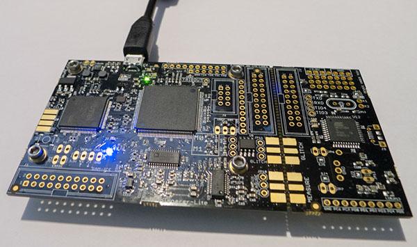
This tutorial uses the CW1173_ChipWhisperer-Lite hardware. No hardware setup is required normally, simply plug in the USB cable:
Note that under no circumstances as part of the setup should you use the CW1173 device to hold up furniture:
=== CW1173 (Lite) Hardware Setup === This tutorial uses the CW1173_ChipWhisperer-Lite hardware. No hardware setup is required normally, simply plug in the USB cable:
Note that under no circumstances as part of the setup should you use the CW1173 device to hold up furniture:
CW1200 (Pro) Hardware Setup
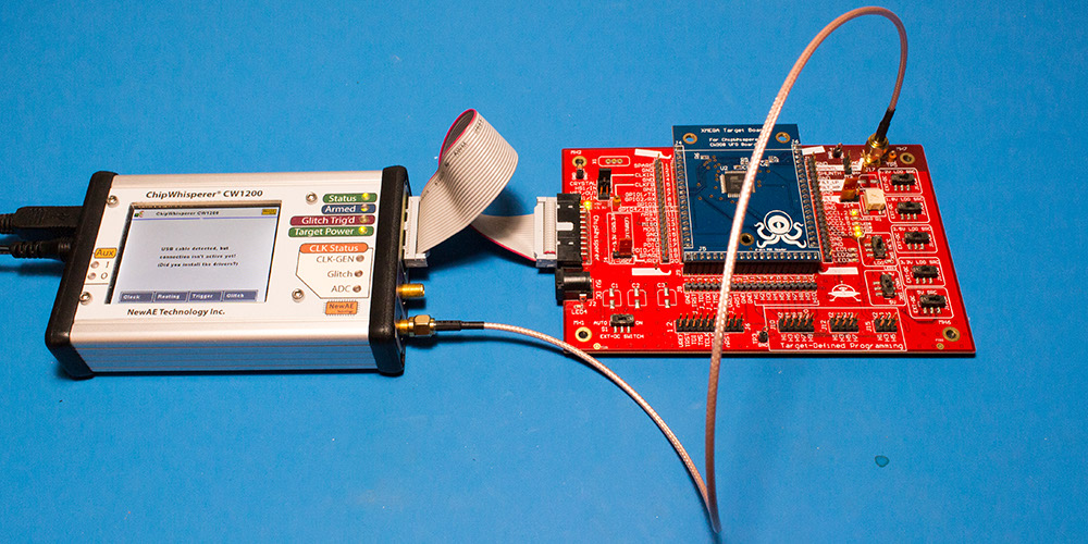
This tutorial uses the CW1200_ChipWhisperer-Pro hardware.
- Remove the ChipWhisperer-Pro main capture hardware, UFO Board, and SMA cable from the ChipWhisperer-Pro case.
- Attached the UFO board to the ChipWhisperer-Pro with the 20-pin cable, and connect the VOUT SMA connector to the MEASURE input.
- Power up the ChipWhisperer-Pro with the 5V DC power adapter, and connect the USB cable to the computer.
- If this the first time powering up, you will need to install the drivers (see CW1200_ChipWhisperer-Pro).
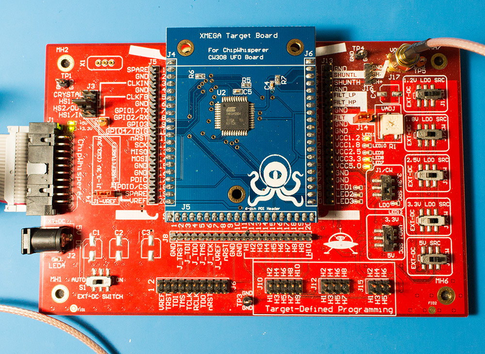
Note if you have modified the UFO board the jumpers may no longer be at default locations. The jumper settings required are:
- XMEGA Target board mounted
- J3 routes HS2/OUT to CLKIN
- J1 set to "J5-VREF" (right two pins shorted)
- J14 set to "FILT" (left two pins shorted)
- "3.3V SRC" switch set to "J1/CW"
=== CW1200 (Pro) Hardware Setup === This tutorial uses the CW1200_ChipWhisperer-Pro hardware.
- Remove the ChipWhisperer-Pro main capture hardware, UFO Board, and SMA cable from the ChipWhisperer-Pro case.
- Attached the UFO board to the ChipWhisperer-Pro with the 20-pin cable, and connect the VOUT SMA connector to the MEASURE input.
- Power up the ChipWhisperer-Pro with the 5V DC power adapter, and connect the USB cable to the computer.
- If this the first time powering up, you will need to install the drivers (see CW1200_ChipWhisperer-Pro).
Note if you have modified the UFO board the jumpers may no longer be at default locations. The jumper settings required are:
- XMEGA Target board mounted
- J3 routes HS2/OUT to CLKIN
- J1 set to "J5-VREF" (right two pins shorted)
- J14 set to "FILT" (left two pins shorted)
- "3.3V SRC" switch set to "J1/CW"
CW308 (UFO) Hardware Setup
Coming soon!
=== CW308 (UFO) Hardware Setup === Coming soon!
Programming the Target
Programming the XMEGA Target
It is assumed that you've already followed the guide in Installing_ChipWhisperer. Thus it is assumed you are able to communicate with the ChipWhisperer CW1173 hardware (or whatever capture hardware you are using). Note in particular you must have configured the FPGA bitstream in the ChipWhisperer-Capture software, all part of the description in the Installing_ChipWhisperer guide.
Assuming this setup is complete, you can confirm you are able to communicate with the hardware by running the example capture of traces given in the CW1173_ChipWhisperer-Lite quick-start.
Programming the Example
Note with the XMEGA target, you need to configure a clock before programming of the device will succeed. Programming of the target device will be done as part of the CW-Capture software setup, discussed next.
Communicating from CW-Capture Software
Next, open the CW-Capture software. Then perform the following steps:
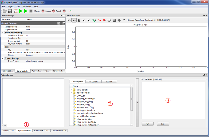
- Switch to the Python Console tab.
- The script selection window (2) lists available example scripts. Scroll down to "connect_cwlite_simpleserial.py" and click on it.
- You will see the script contents appear in the "Script Preview" window (3). You can either hit the "Run" button or double-click the filename of the script to execute it. Do either of those now.
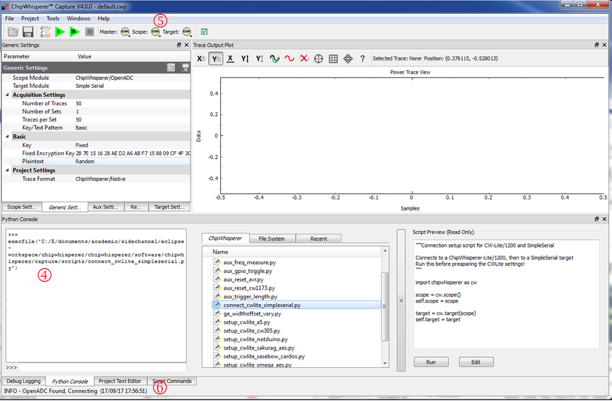
The window should change to indicate the connect succeeded:
- The console lists the exact script that is executed. Note you could have manually executed the script commands line-by-line in this console.
- The "Scope" and "Target" buttons will show as connected.
- The Status Bar will show a connection.
Note in previous software versions, this tutorial took you through manual setup. This can still be done (using the GUI), but instead now the API has been made more powerful, so the example configuration script will be used instead.
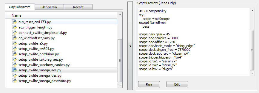
To do so, simply scroll down and select the "setup_cwlite_xmega_aes.py" file:
You'll notice the contents of the script contain the following setup: 1 scope.gain.gain = 45
2 scope.adc.samples = 3000
3 scope.adc.offset = 1250
4 scope.adc.basic_mode = "rising_edge"
5 scope.clock.clkgen_freq = 7370000
6 scope.clock.adc_src = "clkgen_x4"
7 scope.trigger.triggers = "tio4"
8 scope.io.tio1 = "serial_rx"
9 scope.io.tio2 = "serial_tx"
10 scope.io.hs2 = "clkgen"
Line 1: Sets the input ADC gain
Line 2: Sets the number of samples to record as 3000 samples long (this is normally used for the AES algorithm).
Line 3: Sets an offset of 1250 samples from the trigger to when we start recording samples.
Line 4: Sets the trigger as being a "rising edge" trigger.
Line 5: Sets the internal clock generator to 7.37MHz
Line 6: Sets the ADC as running at 4x that clock (so 29.48MHz)
Line 7: Sets the trigger pin as GPIO4 (we previously set the trigger condition as rising edge, so this pin will be the one a rising edge is expected on).
Line 8: Configures GPIO1 as the RX (Input). This is what the XMEGA target expects.
Line 9: Configures GPIO2 as the TX (Output). This is what the XMEGA target expects.
Line 10: Sets the "High-Speed 2" (HS2) pin as having the 7.37MHz clock output.
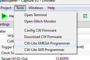
You can now program the XMEGA device! To do so, open the XMEGA Programmer from the Tools menu:
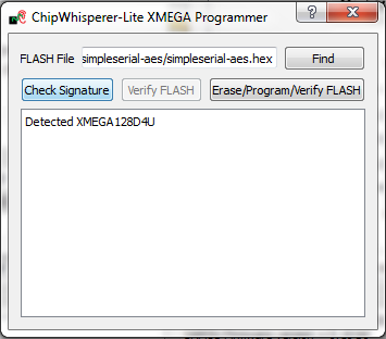
Hit the Check Signature button and confirm the device is detected. If not you may have issues with the clock setup.
Using the Find button, navigate to the
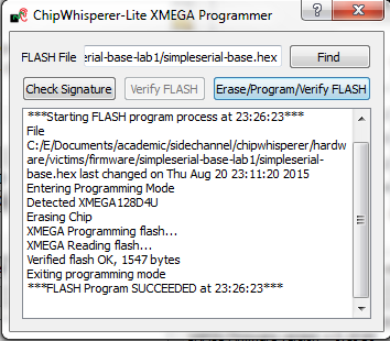
simpleserial-base-cw303.hex(or whatever your hex file is called), which you built earlier with themakecommand. You can then press the Erase/Program/Verify button, and confirm the file is programmed into the XMEGA device:Note the programmer dialog not only shows the successful programming status, but also shows when the
.hexfile was last modified. Always confirm this matches with when you last remember compiling the program -- if it is widely different this suggests you have selected the wrong file!
- You can now close the programming dialog if you'd like. If you're frequently reprogramming the target, you may want to leave this open.
=== Programming the XMEGA Target === It is assumed that you've already followed the guide in Installing_ChipWhisperer. Thus it is assumed you are able to communicate with the ChipWhisperer CW1173 hardware (or whatever capture hardware you are using). Note in particular you must have configured the FPGA bitstream in the ChipWhisperer-Capture software, all part of the description in the Installing_ChipWhisperer guide.
Assuming this setup is complete, you can confirm you are able to communicate with the hardware by running the example capture of traces given in the CW1173_ChipWhisperer-Lite quick-start.
Programming the Example
Note with the XMEGA target, you need to configure a clock before programming of the device will succeed. Programming of the target device will be done as part of the CW-Capture software setup, discussed next.
Communicating from CW-Capture Software
Next, open the CW-Capture software. Then perform the following steps:
- Switch to the Python Console tab.
- The script selection window (2) lists available example scripts. Scroll down to "connect_cwlite_simpleserial.py" and click on it.
- You will see the script contents appear in the "Script Preview" window (3). You can either hit the "Run" button or double-click the filename of the script to execute it. Do either of those now.
The window should change to indicate the connect succeeded:
- The console lists the exact script that is executed. Note you could have manually executed the script commands line-by-line in this console.
- The "Scope" and "Target" buttons will show as connected.
- The Status Bar will show a connection.
Note in previous software versions, this tutorial took you through manual setup. This can still be done (using the GUI), but instead now the API has been made more powerful, so the example configuration script will be used instead.
To do so, simply scroll down and select the "setup_cwlite_xmega_aes.py" file:
You'll notice the contents of the script contain the following setup: 1 scope.gain.gain = 45
2 scope.adc.samples = 3000
3 scope.adc.offset = 1250
4 scope.adc.basic_mode = "rising_edge"
5 scope.clock.clkgen_freq = 7370000
6 scope.clock.adc_src = "clkgen_x4"
7 scope.trigger.triggers = "tio4"
8 scope.io.tio1 = "serial_rx"
9 scope.io.tio2 = "serial_tx"
10 scope.io.hs2 = "clkgen"
Line 1: Sets the input ADC gain
Line 2: Sets the number of samples to record as 3000 samples long (this is normally used for the AES algorithm).
Line 3: Sets an offset of 1250 samples from the trigger to when we start recording samples.
Line 4: Sets the trigger as being a "rising edge" trigger.
Line 5: Sets the internal clock generator to 7.37MHz
Line 6: Sets the ADC as running at 4x that clock (so 29.48MHz)
Line 7: Sets the trigger pin as GPIO4 (we previously set the trigger condition as rising edge, so this pin will be the one a rising edge is expected on).
Line 8: Configures GPIO1 as the RX (Input). This is what the XMEGA target expects.
Line 9: Configures GPIO2 as the TX (Output). This is what the XMEGA target expects.
Line 10: Sets the "High-Speed 2" (HS2) pin as having the 7.37MHz clock output.
You can now program the XMEGA device! To do so, open the XMEGA Programmer from the Tools menu:
Hit the Check Signature button and confirm the device is detected. If not you may have issues with the clock setup.
Using the Find button, navigate to the
simpleserial-base-cw303.hex(or whatever your hex file is called), which you built earlier with themakecommand. You can then press the Erase/Program/Verify button, and confirm the file is programmed into the XMEGA device:Note the programmer dialog not only shows the successful programming status, but also shows when the
.hexfile was last modified. Always confirm this matches with when you last remember compiling the program -- if it is widely different this suggests you have selected the wrong file!
- You can now close the programming dialog if you'd like. If you're frequently reprogramming the target, you may want to leave this open.
Programming the STM32F3 (CW303 Arm) Target
It is assumed that you've already followed the guide in Installing_ChipWhisperer. Thus it is assumed you are able to communicate with the ChipWhisperer CW1173 hardware (or whatever capture hardware you are using). Note in particular you must have configured the FPGA bitstream in the ChipWhisperer-Capture software, all part of the description in the Installing_ChipWhisperer guide.
Assuming this setup is complete, you can confirm you are able to communicate with the hardware by running the example capture of traces given in the CW1173_ChipWhisperer-Lite quick-start.
Programming the Example
Note with the CW303 Arm target, you need to configure a clock before programming of the device will succeed. Programming of the target device will be done as part of the CW-Capture software setup, discussed next.
Communicating from CW-Capture Software
Next, open the CW-Capture software. Then perform the following steps:
- Switch to the Python Console tab.
- The script selection window (2) lists available example scripts. Scroll down to "connect_cwlite_simpleserial.py" and click on it.
- You will see the script contents appear in the "Script Preview" window (3). You can either hit the "Run" button or double-click the filename of the script to execute it. Do either of those now.
The window should change to indicate the connect succeeded:
- The console lists the exact script that is executed. Note you could have manually executed the script commands line-by-line in this console.
- The "Scope" and "Target" buttons will show as connected.
- The Status Bar will show a connection.
Note in previous software versions, this tutorial took you through manual setup. This can still be done (using the GUI), but instead now the API has been made more powerful, so the example configuration script will be used instead.
To do so, simply scroll down and select the "setup_cwlite_stm32f_aes.py" file:
You'll notice the contents of the script contain the following setup: 1 scope.gain.gain = 45
2 scope.adc.samples = 5000
3 scope.adc.offset = 0
4 scope.adc.basic_mode = "rising_edge"
5 scope.clock.clkgen_freq = 7370000
6 scope.clock.adc_src = "clkgen_x4"
7 scope.trigger.triggers = "tio4"
8 scope.io.tio1 = "serial_rx"
9 scope.io.tio2 = "serial_tx"
10 scope.io.hs2 = "clkgen"
11
12 target.baud=38400
Line 1: Sets the input ADC gain
Line 2: Sets the number of samples to record as 5000 samples long (this is normally used for the AES algorithm).
Line 3: Sets an offset of 0 samples from the trigger to when we start recording samples.
Line 4: Sets the trigger as being a "rising edge" trigger.
Line 5: Sets the internal clock generator to 7.37MHz
Line 6: Sets the ADC as running at 4x that clock (so 29.48MHz)
Line 7: Sets the trigger pin as GPIO4 (we previously set the trigger condition as rising edge, so this pin will be the one a rising edge is expected on).
Line 8: Configures GPIO1 as the RX (Input). This is what the ARM target expects.
Line 9: Configures GPIO2 as the TX (Output). This is what the ARM target expects.
Line 10: Sets the "High-Speed 2" (HS2) pin as having the 7.37MHz clock output.
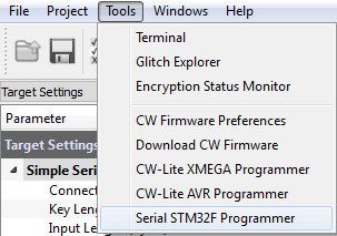
Line 12: Sets the serial communication speed with the target at 38400 baud.You can now program the ARM device! To do so, open the STM32F Programmer from the Tools menu:
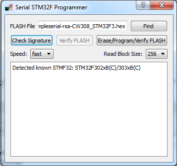
Hit the Check Signature button and confirm the device is detected. If not you may have issues with the clock setup.
Using the Find button, navigate to the
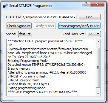
simpleserial-base-CWLITEARM.hex(or whatever your binary is called), which you built earlier with themakecommand. You can then press the Erase/Program/Verify button, and confirm the file is programmed into the XMEGA device:If the software freezes and the verification fails after a long period of time, set the Read Block Size to 64 instead of 256.
Note the programmer dialog not only shows the successful programming status, but also shows when the
.hexfile was last modified. Always confirm this matches with when you last remember compiling the program -- if it is widely different this suggests you have selected the wrong file!If you'd like, you can close the STM32F programmer dialog. If you frequently reprogram the target, you may want to leave it open.
=== Programming the STM32F3 (CW303 Arm) Target === It is assumed that you've already followed the guide in Installing_ChipWhisperer. Thus it is assumed you are able to communicate with the ChipWhisperer CW1173 hardware (or whatever capture hardware you are using). Note in particular you must have configured the FPGA bitstream in the ChipWhisperer-Capture software, all part of the description in the Installing_ChipWhisperer guide.
Assuming this setup is complete, you can confirm you are able to communicate with the hardware by running the example capture of traces given in the CW1173_ChipWhisperer-Lite quick-start.
Programming the Example
Note with the CW303 Arm target, you need to configure a clock before programming of the device will succeed. Programming of the target device will be done as part of the CW-Capture software setup, discussed next.
Communicating from CW-Capture Software
Next, open the CW-Capture software. Then perform the following steps:
- Switch to the Python Console tab.
- The script selection window (2) lists available example scripts. Scroll down to "connect_cwlite_simpleserial.py" and click on it.
- You will see the script contents appear in the "Script Preview" window (3). You can either hit the "Run" button or double-click the filename of the script to execute it. Do either of those now.
The window should change to indicate the connect succeeded:
- The console lists the exact script that is executed. Note you could have manually executed the script commands line-by-line in this console.
- The "Scope" and "Target" buttons will show as connected.
- The Status Bar will show a connection.
Note in previous software versions, this tutorial took you through manual setup. This can still be done (using the GUI), but instead now the API has been made more powerful, so the example configuration script will be used instead.
To do so, simply scroll down and select the "setup_cwlite_stm32f_aes.py" file:
You'll notice the contents of the script contain the following setup: 1 scope.gain.gain = 45
2 scope.adc.samples = 5000
3 scope.adc.offset = 0
4 scope.adc.basic_mode = "rising_edge"
5 scope.clock.clkgen_freq = 7370000
6 scope.clock.adc_src = "clkgen_x4"
7 scope.trigger.triggers = "tio4"
8 scope.io.tio1 = "serial_rx"
9 scope.io.tio2 = "serial_tx"
10 scope.io.hs2 = "clkgen"
11
12 target.baud=38400
Line 1: Sets the input ADC gain
Line 2: Sets the number of samples to record as 5000 samples long (this is normally used for the AES algorithm).
Line 3: Sets an offset of 0 samples from the trigger to when we start recording samples.
Line 4: Sets the trigger as being a "rising edge" trigger.
Line 5: Sets the internal clock generator to 7.37MHz
Line 6: Sets the ADC as running at 4x that clock (so 29.48MHz)
Line 7: Sets the trigger pin as GPIO4 (we previously set the trigger condition as rising edge, so this pin will be the one a rising edge is expected on).
Line 8: Configures GPIO1 as the RX (Input). This is what the ARM target expects.
Line 9: Configures GPIO2 as the TX (Output). This is what the ARM target expects.
Line 10: Sets the "High-Speed 2" (HS2) pin as having the 7.37MHz clock output.
Line 12: Sets the serial communication speed with the target at 38400 baud.You can now program the ARM device! To do so, open the STM32F Programmer from the Tools menu:
Hit the Check Signature button and confirm the device is detected. If not you may have issues with the clock setup.
Using the Find button, navigate to the
simpleserial-base-CWLITEARM.hex(or whatever your binary is called), which you built earlier with themakecommand. You can then press the Erase/Program/Verify button, and confirm the file is programmed into the XMEGA device:If the software freezes and the verification fails after a long period of time, set the Read Block Size to 64 instead of 256.
Note the programmer dialog not only shows the successful programming status, but also shows when the
.hexfile was last modified. Always confirm this matches with when you last remember compiling the program -- if it is widely different this suggests you have selected the wrong file!If you'd like, you can close the STM32F programmer dialog. If you frequently reprogram the target, you may want to leave it open.
Programming Other Targets
Programming other targets typically requires additional tools, such as a target specific programmer or debugger. Please see the wiki page for your target for additional details. Additionally, you should run connect_simpleserial.py and the associated setup_*.py script before moving on to the rest of the tutorial.
=== Programming Other Targets === Programming other targets typically requires additional tools, such as a target specific programmer or debugger. Please see the wiki page for your target for additional details. Additionally, you should run connect_simpleserial.py and the associated setup_*.py script before moving on to the rest of the tutorial.
Completing the Tutorial
Now that the target has the modified firmware, there's only a few steps left to completing the tutorial. Note that if you've closed ChipWhisperer Capture since programming the device, you'll need to rerun the connect_cwlite_simpleserial.py and target setup scripts:
- Open the status monitor under Tools > Encryption Status Monitor.
- Resize the monitor window. The monitor will show sent & received data to the target.
- Hit the Run 1 button (
 ). You may have to hit it a few times, as the very first serial data is often lost. You should see data populate in the Text Out field of the monitor window. Note that each byte of the Text In is incremented in the Text Out field.
Conclusion
In this tutorial you have learned how to build a custom program for the microcontroller on the ChipWhisperer target board. You have programmed the built .hex file into the microcontroller, and confirmed communications with the ChipWhisperer device.
In future labs you will build on this knowledge to attack specific instructions.
Troubleshooting
Issues with compilation:
You may have to generate the .dep and objdir directories manually before make will work:
mkdir .dep mkdir objdir- On Windows 8, you may get an error like fork: resyntaxhighlight temporarily unavailable. This requires you to install an updated mysys.dll. Download from http://www.madwizard.org/download/electronics/msys-1.0-vista64.zip, unzip file, and copy the .dll to
C:\WinAVR-20100110\utils\bin, replacing the existing file.- For the AVR Studio USB Drivers, you'll need to download a Special Update from Atmel.
- You may wish to use the "ChipWhisperer Virtual Machine" on newer Windows systems, which does not require any of the above setup.
