| As of August 2020 the site you are on (wiki.newae.com) is deprecated, and content is now at rtfm.newae.com. |
CW1002 ChipWhisperer Capture Rev2
Contents
Introduction to Capture Hardware
There are three versions of the ChipWhisperer Capture Rev2, also called the CWCR2. They are:
- ChipWhisperer Capture Rev2 in a metal box, part of the ChipWhisperer Complete Kit
- ChipWhisperer Capture Rev2 as a PCB within tubing, part of the ChipWhisperer Simple Kit
- ChipWhisperer Capture Rev2 as a self-made PCB
Fundamentally all of these units are the same. The self-made PCB may of course have dropped certain features, so some of these sections may not be relevant.
System Design
ChipWhisperer Parts
The following figure highlights some of the hardware features of the ChipWhisperer Capture Rev2. Specifics of each area will be discussed in this chapter.
ChipWhisperer Capture PCB.This shows the ChipWhisperer main PCB. Various features are highlighted on this figure.
Removing the Case
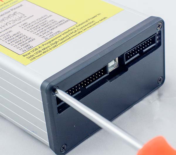
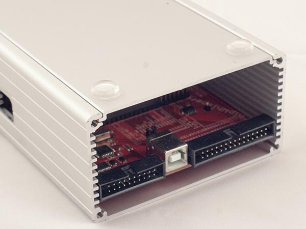
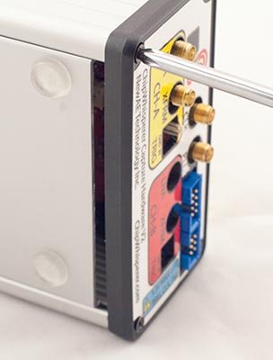
It may be neccessary to access the ChipWhisperer PCB. This is done by removing the rear panel, and sliding out the bottom panel. Note that friction from the front panel may require the two lower front screws to be slightly loosened.
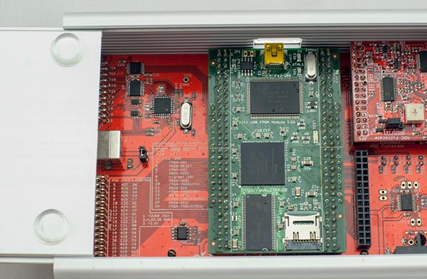
If it's desired to complete remove the main PCB, the front panel will also need to be removed. This is neccesary to reduce the friction on the main PCB such that it can be slid out of the case.
Access to the main PCB is shown in the following figures:
Reflashing the AVR
The AVRUSB portion mentioned in figcwcr2, which is an AT90USB162 device. This chip is programmed to function as a programmer for the AVR or XMEGA device on the Multi-Target board. In many instances it's desired to reprogram this AVR, for example to use it for communications with a SPI target device.
It should be possible to program the AVR by forcing it to revert to the bootloader, a process described below. If this doesn't work, there is also a manual override available.
Programming Software
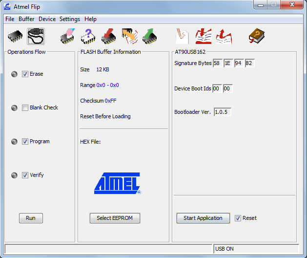
Programming the AVR-USB is done via Atmel's FLIP software, available from Atmel's Website. As an alternative you can use the DFUProgrammer software, which is open-source and works on both Windows and Linux.
This programmer will interact with a bootloader that is always resident on the AVR-USB device. Once it becomes active it will require you to install a new driver, since it appears to your computer as a completely different device. Both FLIP and dfuprogrammer come with drivers, so just point your New Device Found wizard to the appropriate location if they aren't automatically picked up. For FLIP it would be something like C:\Program Files (x86)\Atmel\Flip 3.4.5\usb.
The sequence of steps to program a new .hex file into the AVR are as follows:
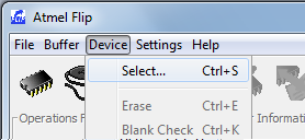
Run the FLIP software. Select the Device-Select option (or press Ctrl+S) the first time you run the software
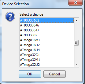
And select the AT90USB162 device. You should only have to do this once.
- Force the AVR-USB Bootloader to run before the next step. Note the bootloader will automatically time out if no command is received, so once you have the bootloader running proceed to step 4. For details of getting the bootloader running see bootloader-normal.
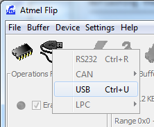
Press the USB button, and hit the USB option:
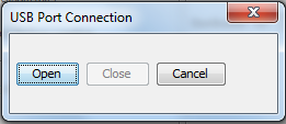
Press the Open button, if this fails you are not in bootloader mode.
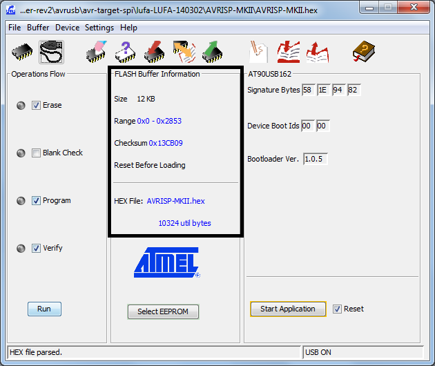
The main window should light up with options! It will now look something like this:
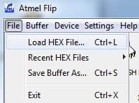
Load a new HEX file. You can find them in the ChipWhisperer git in the
chipwhisperer\hardware\capture\chipwhisperer-rev2\avrusbfolder of ChipWhisperer releases (or in GIT).Confirm that the window now reflects your selected file. Press the Run button on the left side of the screen to start the programming.
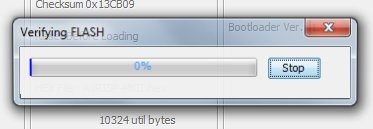
You should briefly see some indication of programming and verification pop up. If not try pressing the Run button again!
Finally press the Start Application button. This will cause the bootloader to exit and your application to start.
Jumping to Bootloader
Normally you can jump to the bootloader without requiring the manual override. If invalid or corrupt code has been loaded into the AVR, the manual override will be required. The specific method of jumping to the bootloader depends which mode the AVR is currently in, the default is the AVR-Programmer mode (e.g. all ChipWhisperer units are shipped in this mode).
From AVR-Programmer Mode
- Start AVRStudio
- Connect to the AVR Programmer. You DO NOT need an AVR connected, you may receive a message that the SPI command has failed, however you can ignore that.
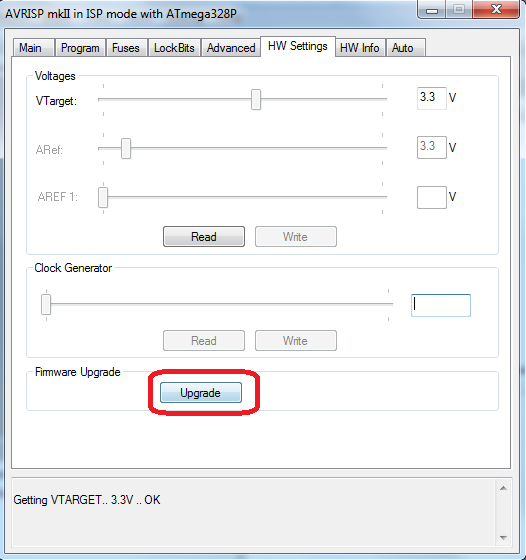
Switch to the HW Settings tab and press the Upgrade button:
- The device will now jump to the bootloader. If pressing the Upgrade button did nothing you may need to use the manual mode described below - CWCR2 devices purchased before July 1st, 2014 did not have the software-based upgrade feature.
Forcing Bootloader to Run
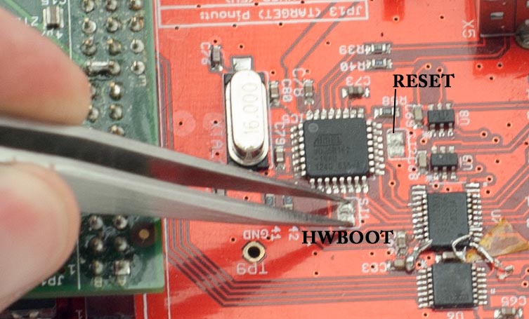
See the following figure for location of the two jumper pads. You will need to short them with something metallic such as tweezers or a small flat-head screwdriver. In a pinch a coin such as a dime can be used. The required operations are:
- Plug the USB-A Cable in
- Short the HWBOOT jumper (SJ1)
- With the HWBOOT jumper shorted, temporarily short the RESET jumper (SJ2)
- Release the HWBOOT jumper
This will cause the AVR to jump to the bootloader, and your programming software can be run.
This shows the two jumper pads (SJ1 and SJ2). SJ1 is the HWBOOT feature, and SJ2 is the RESET feature.
ChipWhisperer-Capture Rev2 Specific Software Instructions
Installing Drivers for CaptureRev2 on Windows
The following is specific to ChipWhisperer Capture Rev2 hardware. Using the mini-usb cable, plug in the ChipWhisperer Capture Rev2. Note that only an internal LED will turn on when this happens - the LEDs on the front panel are controlled by the internal FPGA. They will not be active until you actually communicate with the unit.
Windows should pop up a New Hardware Found dialog, but frequently may not. In which case force the driver to update using the following:
- Open the Device Manager. On Windows 7 simply search Device Manager from start menu
- Find the Cypress EZ-USB Item, which should have a yellow (!) mark
- Click Update Driver
- Once this happens, you'll be able to point Windows to the location of the drivers. Some releases contain drivers, so you can attempt to point the wizard to the folder
c:\chipwhisperer\hardware\capture\chipwhisperer-rev2. If you don't have drivers, you can download them from the release page on ChipWhisperer.
Note as of version 0.07 of the ChipWhisperer release you DO NOT need to install Java. Previous versions required this, so you may see reference to that in videos or other documentation. Be confident you can now avoid installing Java when running ChipWhisperer.
Finally, we can configure the ChipWhisperer-Capture software to communicate with the hadware. To do so you need to configure the FPGA loader program, microcontroller program, and FPGA bitstream.
- Run ChipWhisperer-Capture by double-clicking CWCapture.pyw in
c:\chipwhisperer\software\. (Note: this simply calls ChipWhispererCapture.py inc:\chipwhisperer\software\chipwhisperer\capture\, if you have trouble try double-clicking on the ChipWhispererCapture.py instead). - As the scope, select the ChipWhisperer device, and ensure on the Scope tab ensure you have selected the appropriate hardware, such as the rev2 device
- Under the Tools menu select Config CW Firmware (NB: If this does not appear as a menu option, double-check you have selected the correct scope).
- In the pop-up dialog, you may need to configure the location of several files. If they are blank set as follows:
- USB Firmware:
c:\chipwhisperer\hardware\capture\chipwhisperer-rev2\ezusb-firmware\ztex-sdk\examples\usb-fpga-1.11\1.11c\openadc\OpenADC.ihx - FPGA .zip (RELEASE):
c:\chipwhisperer\hardware\capture\chipwhisperer-rev2\cwrev2_firmware.zip
- USB Firmware:
- Under the Tools menu selection Download CW Firmware with the ChipWhisperer device attached. If this works you will see a message in the Debug Logging window about firmware upload successful. If this fails check the output of the console to see what went wrong.
Note as of version 0.09 of the ChipWhisperer release the tool will automatically download firmware to unprogrammed FPGAs. You do not need to explicitly run this tool before connecting, however it is still useful for debugging or forcing the loading of new firmware. In addition you must have selected the proper scope and ChipWhisperer model for the firmware download to work - this is a change from 0.08 which just blindly presented the menu choice.
You can see a Video of the Installation Process. Note the drivers are now signed, so you will no longer see a warning about unsigned drivers.
Using the AVR Programmer on Windows
Next, you will need to program the AVR itself. On Windows we will make use of the free AVR Studio 4.19. You can find a direct link here: Direct Link to AVR Studio 4.19 Binary. Note it is possible to use
avrdude, a command-line program which is part of WinAVR instead if you wish. However since many people find the graphical interface of AVRStudio easier, this guide will use AVRStudio. Be sure to install the USB drivers as part of the package.warning
If using Windows 8.1, AVRStudio 4.19 may not work correctly. In particular DO NOT install the USB Drivers as part of the installation package as mentioned above. Instead first install the latest stand-alone AtmelUSBInstaller version.
You can see additional details on the following thread: http://www.avrfreaks.net/forum/avrisp-mk2-programmer-windows-81. If you have already installed AVRStudio 4.19 you may have to remove the associated drivers, please see the linked thread for details.
- Plug in the USB-A Connector on the rear side of the ChipWhisperer Rev2. This should trigger the driver installation, which will detect the device as a AVR-ISP MK2.
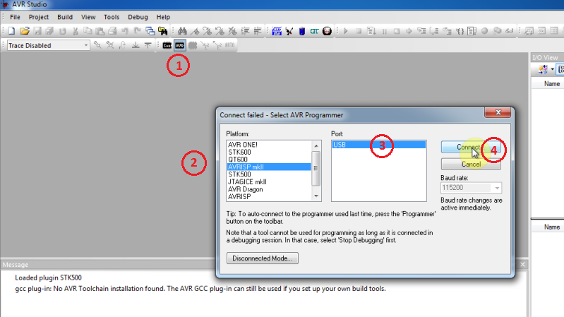
Once AVR Studio is installed, open the main window. From the toolbar select either the Con or AVR icon, and select the AVR-ISP MK-II Device:
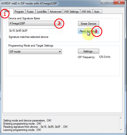
In the window that opens, select the Main tab. Select the device type as AtMega328P, and hit Read Signature. You should get an indication that the device signature was successfully read!
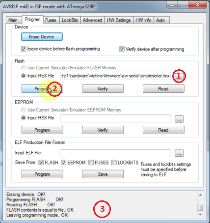
Finally we can program the chip. To do so switch to the Program tab, select the
simpleserial.hexfile that was generated in Step 4, and hit Program. If it's successful you should see some output data saying so.
You can see a Video of the Target Build Procedure:
Using the AVR Programmer on Linux
To use the AVR Programmer from Linux, you again need to pass control of the device to a special group. Create a file called /etc/udev/rules.d/99-avrisp.rules . The contents of this file should be:
# allow users to claim the device
SUBSYSTEM=="usb", ATTRS{idVendor}=="03eb", ATTRS{idProduct}=="2104", MODE="0664", GROUP="plugdev"
You'll have to add yourself to the plugdev group if you haven't already:
$ sudo usermod -a -G plugdev YOUR-USERNAME
And reset the udev system:
$ sudo udevadm control --reload-rules
Finally log out & in again for the group change to take effect.
You can now use the programmer with the 'avrdude' software.
I/O Connections
Target-IO Connections
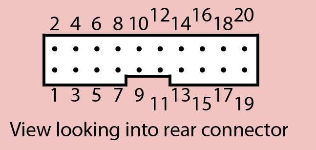
The TargetIO connector is on the rear side of the ChipWhisperer Capture R2 (CWCR2), and is a 20-pin connector. The pinout can be found on the label on the top-side of the CWCR2, or marked on the top-side silk-screen for the CWCR2.
Looking into the male connector on the ChipWhisperer Capture Rev2, the following is the pinout:
The pinout is as follows:
| Number | Name | Dir | Description |
|---|---|---|---|
| 1 | +VUSB (5V) | O | Raw USB Power. Not filtered. |
| 2 | GND | O | System GND. |
| 3 | +3.3V | O | +3.3V from FPGA Power Supply. Very high current can be supplied. |
| 4 | FPGA-HS1 | I/O | High Speed Input (normally clock in). |
| 5 | PROG-RESET | I/O | Target RESET Pin (AVR Programmer). |
| 6 | FPGA-HS2 | I/O | High Speed Output (normally clock or glitch out). |
| 7 | PROG-MISO | I/O | SPI input: MISO (for SPI + AVR Programmer). |
| 8 | VTarget | I | Drive this pin with desired I/O voltage in range 1.5V-5V. |
| 9 | PROG-MOSI | I/O | SPI output: MOSI (for SPI + AVR Programmer). |
| 10 | FPGA-TARG1 | I/O | TargetIO Pin 1 - Usually UART TX. |
| 11 | PROG-SCK | I/O | SPI output: SCK (for SPI + AVR Programmer). |
| 12 | FPGA-TARG2 | I/O | TargetIO Pin 2 - Usually UART RX. |
| 13 | PROG-PDIC | I/O | PDI Programming Clock (XMEGA Programmer), or CS pin (SPI). |
| 14 | FPGA-TARG3 | I/O | TargetIO Pin 3 - Usually bidirectional IO for smartcard. |
| 15 | PROG-PDID | I/O | PDI Programming Data (XMEGA Programmer). |
| 16 | FPGA-TARG4 | I/O | TargetIO Pin 4 - Usually trigger input. |
| 17 | GND | O | |
| 18 | +3.3V | O | |
| 19 | GND | O | |
| 20 | +VUSB (5V) | O |
PLL Connections
Expansion & Power Connections
Front-Panel Analog
Internal Connections and Jumpers
The main ChipWhisperer Capture Rev2 PCB has several jumpers and connectors. This section explains the use of these jumpers. Note you will need to remove the case to access these jumpers.
JTAG
Power Jumpers
PLL Enable and I2C
GND Test-Points
ChipWhisperer SPI Driver
Installing HIDAPI
Communication with the HID USB interface requires a Python package, hidapi. Follow these steps to install:
If you are using WinPython or have pip installed, try the following:
pip install hidapi
If you do not have pip, you can also try easy_install:
easy_install hidapi
If you do not have a suitable C compiler installed, you will see the following error from those:
error: Unable to find vcvarsall.bat
- If you received the
vcvarsall.baterror, continue with this guide. Download and install MinGW <http://sourceforge.net/projects/mingw/files/latest/download?source=files> - Once MinGW is installed, right-click on the mingw32-gcc-g++ and select Mark for Installation
- Under the Installation menu, select Apply Changes. Once this completes close the dialog & mingw window.
Create a file with the name
C:\PYTHONG_PATH\Lib\distutils\distutils.cfg, where PYTHON_PATH is your Python path. If you have used WinPython the path might be something likeC:\WinPython-32bit-2.7.6.4\python-2.7.6\Lib\distutils\distutils.cfg. The contents of this file must be:[build] compiler=mingw32
- Re-run the
pip install hidapioreasy_install hidapi, looking for the final output Successfully installed hidapi.
NOTE: It appears sometimes the resulting hid.pyd file causes a crash on Windows. If this is the case a pre-compiled .pyd file is available for use.
Re-Programming the AVR
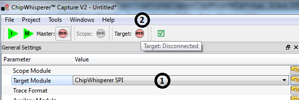
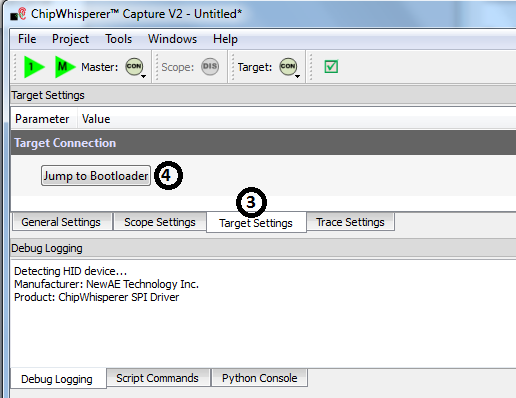
You need to use the ChipWhispererSPI.hex file in the AVR-USB. See the details earlier in this guide for reprogramming instructions.
