| As of August 2020 the site you are on (wiki.newae.com) is deprecated, and content is now at rtfm.newae.com. |
Difference between revisions of "SAKURA-G Target"
| Line 31: | Line 31: | ||
[[File:sakuragyoutube.png|link=http://www.youtube.com/watch?v=hykeV8DCf2M&hd=1]] | [[File:sakuragyoutube.png|link=http://www.youtube.com/watch?v=hykeV8DCf2M&hd=1]] | ||
| + | == Hardware == | ||
{{Template:Hardware}} | {{Template:Hardware}} | ||
Latest revision as of 10:25, 1 May 2018
Preparing the SAKURA-G Hardware
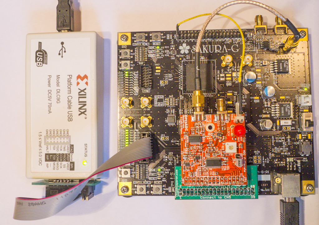
The SAKURA-G must be prepared for use with the ChipWhisperer system. This requires the OpenADC device mounted using an interposer PCB. In addition the SMA connector must route the power measurement, and the trigger signal must be connected. This assumes the FPGA #1 on the SAKURA-G has been programmed with the AES example.
A Xilinx Platform USB Cable or similar is used for programming. The complete setup looks as follows:
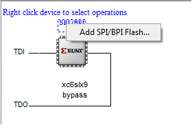
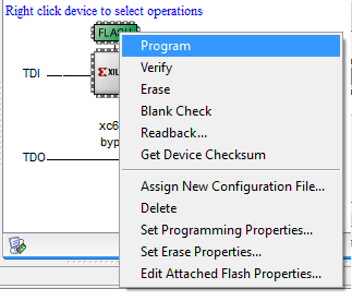
You must then run Xilinx Impact program, and have it detect the Spartan 6 LX9 device. You can then add a SPI Flash:
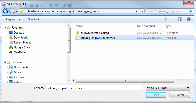
This will prompt you to specify the PROM file. This file is located in chipwhisperer\hardware\capture\sakura-g\sakurag_ise_project\sakurag-chipwhisperer.mcs.
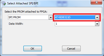
Finally select the SPI Flash Type. Confirm the part number by looking at part U13 on the SAKURA-G, just to the right of the LX9 FPGA.
You can now program the SPI Flash. This step will take some time to complete. Once this is done you have a working ChipWhisperer system.
Running SAKURA-G Example
The SAKURA-G has an example script shipped with the ChipWhisperer release, which can be run from the ChipWhisperer-Capture environment.
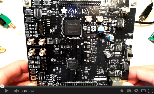
You can see a Video of the system working on YouTube:
