| As of August 2020 the site you are on (wiki.newae.com) is deprecated, and content is now at rtfm.newae.com. |
Difference between revisions of "CW308T-AURIX"
(→Modifying Boot Header) |
|||
| Line 30: | Line 30: | ||
== Modifying Boot Header == | == Modifying Boot Header == | ||
| − | To access some features of the TC233LP, such as the Lockstep control and disabling boot pins, the boot header at the beginning of the hex file must be modified. One way to do this is to use the "Edit" button in Memtool. After selecting the first memory range (should begin with 0xA0000000), hit "Edit". Most of the important settings are in the final 2 bytes of the second word (address 0xA0000004). | + | To access some features of the TC233LP, such as the Lockstep control and disabling boot pins, the boot header at the beginning of the hex file must be modified. One way to do this is to use the "Edit" button in Memtool. After selecting the first memory range (should begin with 0xA0000000), hit "Edit". Most of the important settings (including lockstep control and boot control) are in the final 2 bytes of the second word (address 0xA0000004). |
| + | |||
| + | After modifying the boot header, you'll need to calculate the CRC32 of the header for addresses 0xA0000000 to 0xA0000017, as well as its compliment (bitwise NOT). A resource like https://www.lammertbies.nl/comm/info/crc-calculation.html can be used to calculate the CRC. Make sure the input type is hex. The CRC32 should go in address 0xA0000018, while its compliment should go in address 0xA000001C. For example, the full boot header for lockstep enabled operation should be: 00000000 B3590170 00000000 00000000 00000000 00000000 964C0E85 69B3F17A. | ||
| + | |||
| + | Note that the boot header must be manually edited each time a project is recompiled. One way to avoid this is to edit the startup file that sets the boot header. This is included in the hal/aurix folder in ChipWhisperer's firmware directory as crt0-tc2x.S. The boot header can be found on lines 72 to 79. Note that the CRC32/compliment still has to be calculated for lines 72 to 77, replacing the values of lines 78 and 79. | ||
| − | |||
== Schematic and Layout == | == Schematic and Layout == | ||
Revision as of 06:30, 7 September 2018
| CW308T-AURIX | |
|---|---|
 | |
| Target Device | Infineon TC233LP |
| Hardware Crypto | Yes |
| Status | In Developement |
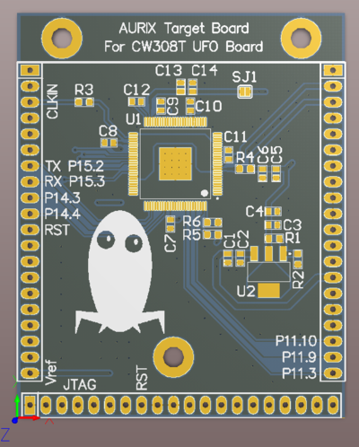
This board supports the Infineon TC233LP microcontroller.
Contents
Power Supply
The core of the TC233LP chip runs from a 1.3v supply that is generated from an on-board regulator. The I/O buses are supplied with 3.3v.
Security Features
The TC233LP has an additional Lockstep core that runs the same instructions as the Master core (CPU0). The outputs of these cores are compared and mismatches are reported in the Safety Management Unit of the chip. This feature can only be enabled by editing the boot header of the resulting hex file.
Programming
Programming of the AURIX board can currently only be done over JTAG with the Infineon DAP miniWiggler v3 using Infineon Memtool. To program the AURIX chip, begin by plugging in the miniWiggler to J6 on the CW308 board. Next, open Memtool.
Next, you'll need to add a target for the TC233LP chip. Navigate to Target > Browse and hit New. Select "Use a default target configuration" and find "Application Kit with TC234 (DAS)" under "Application Kits (DAS)", then hit "Finish". Hit "Connect". If "Ready for Memtool Command" appeared next to it, everything went smoothly.
To actually program the device, open your hex file using "Open File..." on the left hand side. Click on the address beginning with 0xA and hit "Add Sel.>>". Finally, hit Program press the nRST button on the CW308. Current versions of the HAL will light up LED1 upon starting, so if this LED is on, your program has been successfully flashed.
Building Projects
Modifying Boot Header
To access some features of the TC233LP, such as the Lockstep control and disabling boot pins, the boot header at the beginning of the hex file must be modified. One way to do this is to use the "Edit" button in Memtool. After selecting the first memory range (should begin with 0xA0000000), hit "Edit". Most of the important settings (including lockstep control and boot control) are in the final 2 bytes of the second word (address 0xA0000004).
After modifying the boot header, you'll need to calculate the CRC32 of the header for addresses 0xA0000000 to 0xA0000017, as well as its compliment (bitwise NOT). A resource like https://www.lammertbies.nl/comm/info/crc-calculation.html can be used to calculate the CRC. Make sure the input type is hex. The CRC32 should go in address 0xA0000018, while its compliment should go in address 0xA000001C. For example, the full boot header for lockstep enabled operation should be: 00000000 B3590170 00000000 00000000 00000000 00000000 964C0E85 69B3F17A.
Note that the boot header must be manually edited each time a project is recompiled. One way to avoid this is to edit the startup file that sets the boot header. This is included in the hal/aurix folder in ChipWhisperer's firmware directory as crt0-tc2x.S. The boot header can be found on lines 72 to 79. Note that the CRC32/compliment still has to be calculated for lines 72 to 77, replacing the values of lines 78 and 79.
Schematic and Layout
See GIT Repo for design files.