| As of August 2020 the site you are on (wiki.newae.com) is deprecated, and content is now at rtfm.newae.com. |
CW308T-MEGARF
This is a BETA target and not yet available. This wiki page will continue to be updated until release.
| CW308T-MEGARF | |
|---|---|
 | |
| Target Device | Atmel AVR |
| Target Architecture | 8-bit Harvard |
| Hardware Crypto | Yes |
| Design Files | GITHub link |
| Programmer |
CW-Integrated (ISP) Atmel ICE (ISP/JTAG) |
| Status | BETA (Bug fixes needed) |
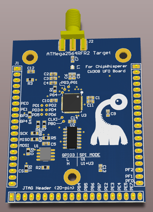
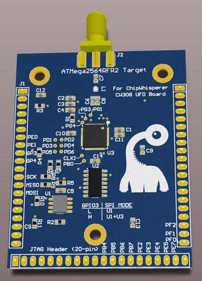
This target is for the ATMega2564RFR2. This makes a great target for exploring IoT technologies, such as mesh networking protocols.
Contents
Usage Notes
Internal / External DVDD Supply
By default the MegaRF will provide the DVDD supply using a regulator inside the MegaRF chip. If you wish to use an external supply you will have to use the VADJ setting on the CW308 to set the DVDD supply to be slightly higher than 1.8V, which would cause the MegaRF on-board regulator to shut down.
In our experimentation the internal DVDD regulator worked fairly well, and did not add significant noise to any measurements.
SPI Connections
There is a SPI flash chip connected to the ATmegaRF2564RFR2. During development you may require an external programmer to load this flash chip, and the MegaRF must be disconnected to do this safely. If you do not disconnect the MegaRF SPI lines & try holding the MegaRF in reset to tri-state the SPI lines, you may end up accidentally loading an ISP programming command.
GPIO3 is normally used to switche the 4066 electronic switch from connecting the external SPI connections between the SPI-Flash memory chip and the MegaRF device. You must set GPIO3 high to allow programming of the MegaRF chip, otherwise it is pulled low which disconnects the MegaRF.
Programming
The ChipWhisperer's AVR programmer supports this target directly. No external programmer is required.
Board Layout
See GIT Repo for gerber files.
Radio Usage
Note NO ANTENNA is provided as the board is sold only as a sub-assembly and not designed to be used as a radio transmitter. Mounting a 2.4 GHz radio antenna (SMA, NOT reverse-polarity SMA) like Digi-Key P/N 1475-1014-ND could potentially require you to meet FCC/CE guidelines for RF emissions and is UNSUPPORTED USAGE.
Errata
-02 Version
Balun pinout is incorrect and will not work.
-01 Version
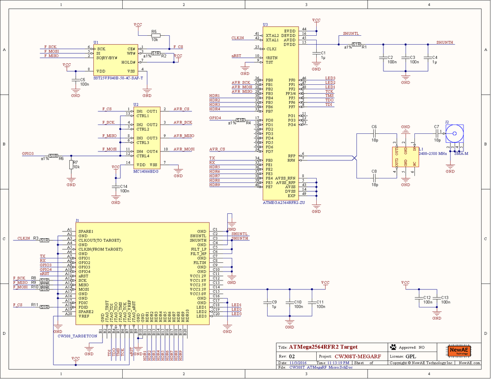
The following is the original (-01) schematic. The -01 PCBs were never publicly released and used during development only. The following changes were made in -02:
- MOSI/MISO was switched on Atmel device (requires PCB fix on -01, or PCB will not work)
- TST connected to ground (requires PCB fix on -01, or PCB will not work)
- CLKI pull down
- GPIO3 is now optionally in control of 4066 instead of being hardwired
- Serial resistors added on SCK/MISO/MOSI lines


