| As of August 2020 the site you are on (wiki.newae.com) is deprecated, and content is now at rtfm.newae.com. |
VISA Connected Oscilloscope
VISA Connected Oscilloscope
Supported Scopes
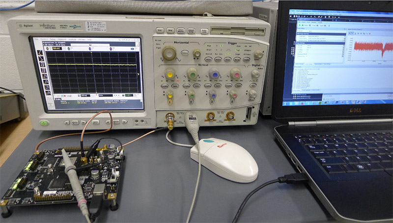
The following scopes have been tested with this system:
- Agilent MSO 54831D
Example of Connecting to Agilent MSO 54831D
Connect the scope and computer using one of these two methods:
- Connect the computer and scope to the same network, and determine the scope's IP
- Connect the computer and scope using a physical ethernet cable and make a network:
- Set the host computer to use a fixed IP on the ethernet connection i.e. set to 192.168.2.1. You may also need to set a fixed ethernet speed, not using the 10/100/1000 auto-detection.
- Set the scope to use a fixed IP on the same subnet as the computer, and set the gateway to the computer's IP address. This example assumes you configured the scope's IP to 192.168.2.100 and gateway to 192.168.2.1.
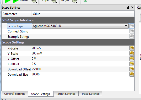
Run the ChipWhisperer-Capture window. Select the VISA Oscilloscope module, and switch over to the scope settings page. Select the MSO54831D module:
Determine the VISA connection string. There is a drop-down list with an example connection string, you can use that as your base. This string tells VISA where to find the oscilloscope, in this case over a TCP/IP connection:
- Hit 'Connect', and hope everything works, the scope 'CON' should go green. If things don't work look for hints from the VISA error messages. You may not have network connectivity to the scope, may not have the VISA instance working on the scope, etc.
- Set the driver for the target module (in this example SASEBO-GII, serial or any other works too), and connect to the target device.
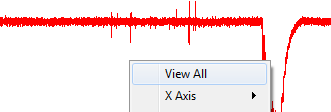
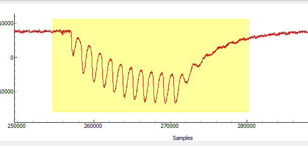
Run a 'Capture 1'. At this point things might be setup grossly incorrectly, so use the 'View All' to see where your signal went:
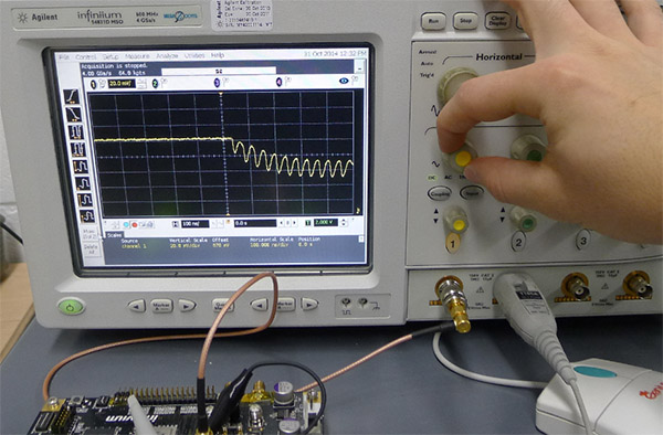
Either by changing settings via the GUI or by fiddling with knobs on the scope, get a nice waveform. This will probably mean adjusting the trigger, offset level, coupling, etc:
With a suitable waveform, we need to only display the portion of interest to us. By default the scope is probably using 50% of the waveform before the trigger, so you might need to zoom in around the middle/trigger event:
You can use the download offset and size to cause only the data of interest to be transferred to the screen. If you transfer too much data you'll end up with huge traces on disk, so try to scale this down as much as possible:
After which you can fine-tune it by again doing several 'Capture 1' events, note you will need to use a 'Zoom All' when changing these settings, since the offset will change:
- Switch to your recording module of interest, and change any settings if required.
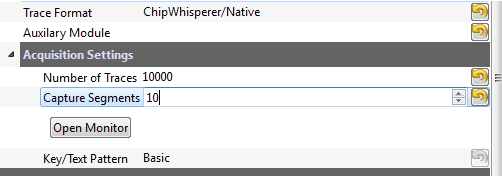
Set the required number of traces. You'll probably want to segment to recording to avoid issues with massive disk files or running out of memory:
- Run your capture & break the system as any other target/scope would.
