CW503 Probe Power Supply
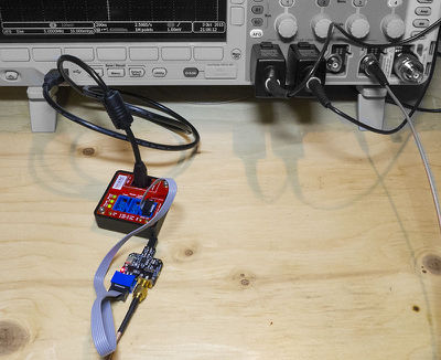
The CW503 provides a handy power supply for both the differential probe and the LNA. Multiple probes can be connected to a single power supply. The following shows the internal block diagram of the CW503 probe power supply:
The use of isolated DC-DC converters allows you to use connected probes without worry about ground loops. Note the probe is not designed for use at high isolation voltages (>30V).
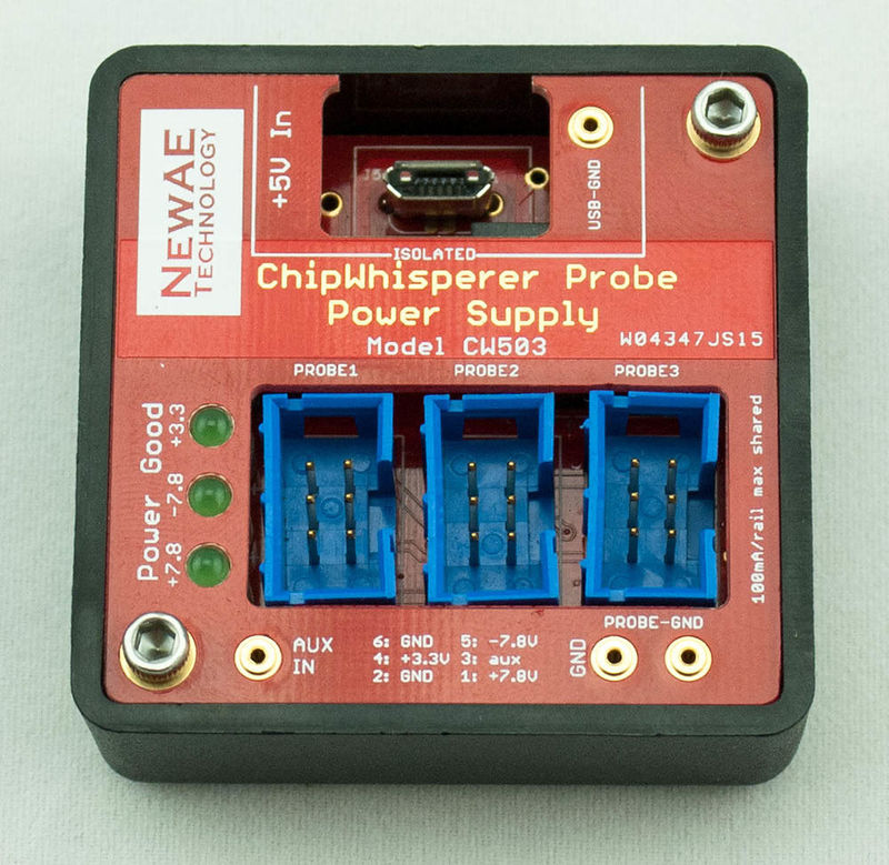
The power supply uses a micro-USB jack, allowing you to power the probe from front-pane USB ports on some instruments (be careful of current limits if using this method):
Alternatively the probe comes with a high-quality 5.0V wall-wart adapter, which has been selected for minimum noise input to the CW503.
Front-Panel Connections
The following can be found on the front panel of the device:
Power Good LEDs:
The probe PSU monitors the +7.8V, -7.8V, and +3.3V outputs. If these outputs fall below the required setpoints the LEDs extinguish. This is normally due to excessive current draw or a short on one of the output lines.
6-Pin Probe PSU Connectors:
This probe supply connectors use the same pinout as our Low Noise Amplifier (CW502) and Differential Probe (CW501). The pinout is as follows:
Pin Name 1 +7.8V Out 2 GND 3 Aux Out 4 +3.3V Out 5 -7.8V Out 6 GND PROBE-GND Pin Header:
This pin header connects to the GND pins on the 6-pin connector.
AUX-IN Pin Header:
This pin header connects to the "Aux Out" pin on the 6-pin connector.
USB-GND Pin Header:
This pin header connects to the USB negative (ground). You can connect this to the PROBE-GND to remove the isolation, or use a resistor if you want to reduce voltage differential without directly connecting them.


