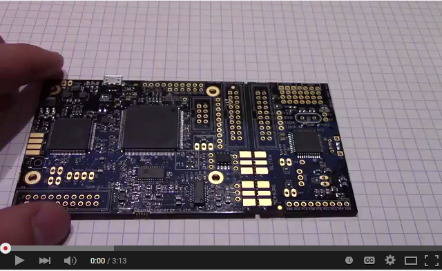
CW1173 ChipWhisperer-Lite
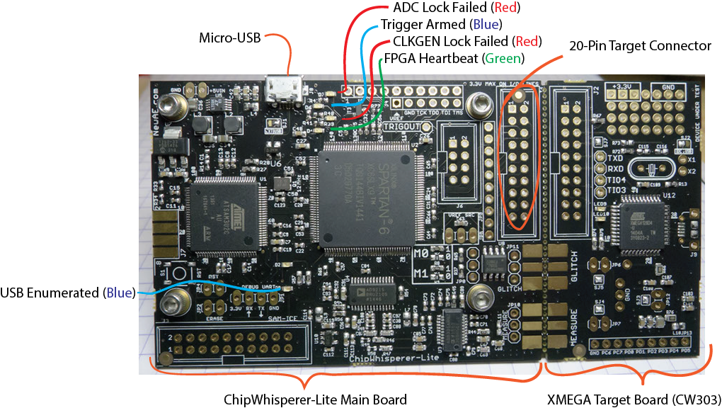
The ChipWhisperer-Lite Bare Board consists of two main parts: a multi-purpose power analysis capture instrument, and a target board. The target board is a standard microcontroller which you can implement algorithms onto. For example if you wish to evaluate an AES library, you can program that library into the target board and perform the power analysis.
Quick-Start Guide
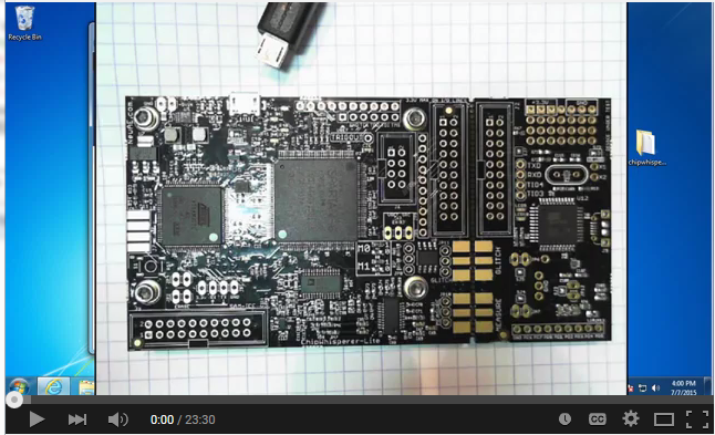
You can see a Video of the quickstart guide, which will take you through all the setup items discussed here:
Connection Quick-Start
- Follow the Installing ChipWhisperer instructions for the ChipWhisperer software and its prerequisites.
- Connect ChipWhisperer-Lite, install USB Drivers:
- Windows:
- Plug micro-USB cable into ChipWhisperer-Lite
- If the "New Hardware Found" wizard doesn't prompt you for drivers, go to the control panel and find the "ChipWhisperer-Lite" device, and select "Update Drivers".
- You can find drivers in
c:\chipwhisperer\hardware\capture\chipwhisperer-lite\. You will likely need to extract them from thecwlite_usb_driver.zipfile. If so simply extract them somewhere (i.e. your desktop), and then point the new hardware found wizard to that location.
- Linux:
Driver installation is not required, but if you do not update the 'udev' system, you will be unable to run ChipWhisperer-Capture as a regular user. To update the udev system, first make sure the ChipWhisperer-Lite is Make a file called
/etc/udev/rules.d/99-cwlite.rules. The contents of this file should be:# allow users to claim the device SUBSYSTEM=="usb", ATTRS{idVendor}=="2b3e", ATTRS{idProduct}=="ace2", MODE="0664", GROUP="plugdev"Add your username to the plugdev group:
$ sudo usermod -a -G plugdev YOUR-USERNAME
And reset the udev system:
$ sudo udevadm control --reload-rules
- Finally log out & in again for the group change to take effect.
- Connect the micro-USB cable
- MAC:
- No special installation required - must ensure you have installed libusb via homebrew (see instructions at MacOSX_Installation).
Run ChipWhisperer-Capture. This can be done from one of three ways:
- Double-click on
CWCapture.pywin thechipwhisperer\softwarefolder. You must have installed Python into your path for this to work. - run
python CWCapture.pywfrom thechipwhisperer\softwarefolder using a command prompt with Python in the path. - run
python CWCaptureGUI.pyfrom thechipwhisperer\software\chipwhisperer\capture\uidirectory.
The last option is the most reliable, in that it should always work on all platforms. If it doesn't start look for possible missing modules or other useful errors.
hint
The first time you run ChipWhisperer-Capture or -Analyzer, the default setup of the screen is somewhat insane. You can drag windows around or close them to make it look more like the demos here. See the Video quickstart guide as well for details of that.
- Double-click on
From the "Scripts" directory, run the
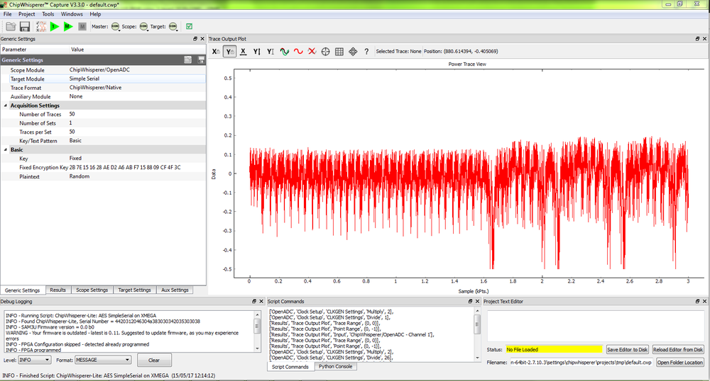
ChipWhisperer-Lite: AES SimpleSerial on XMEGAscript:This should connect to the ChipWhisperer-Lite, program the FPGA, and run a few captures. Your screen should look something like this now:
If the previous step fails, you may need to set the path for the "firmware". This is done by going to the "Tools" menu and selecting the "Config CW Firmware" option. Note on MAC OS X a special command is required instead sometimes, see MacOSX_Installation.
From there, hit the "FIND" button beside the "FPGA .zip (Release)" option. Point it to the file located at
chipwhisperer/hardware/capture/chipwhisperer-lite/cwlite_firmware.zipon your filesystem.- Your ChipWhisperer-Lite is now connected. See the next section for details of the demo attack.
Capture and Attack Quickstart
- See Tutorial_B5_Breaking_AES_(Straightforward)for details. Note the hardware setup is slightly different -- but you can skip to step 5.5.3, and should be able to pick up from there. Be sure to use the
ChipWhisperer-Lite: AES SimpleSerial on XMEGAscript instead of the one referenced in step 5.5.3.
Important Bugs/Caveats
The following includes various things that might trip you up:
- If you save the project before running the capture, you can specify any directory. Traces will be copied to the appropriate location during capture.
- If you save the project after running the capture, you must save the project to the same directory that "default-data-dir" exists in. This is normally the folder from where you invoked the Python GUI.
- There are a few warnings/exceptions that come up (i.e. divide-by-zero). Generally just keep going and see if things are still working. A number of those are on the TODO list to fix but I didn't get around to it yet.
- The "Total Ops" window which checks for proper AES operation requires PyCrypto to be installed.
- By default the XMEGA device was programmed with a partial AES implementation only. This is done to avoid any crypto export issues. This does not affect your side-channel analysis, but be aware the returned value might not appear to be correct (since only the first couple rounds of AES occurred).
Basic Usage Instructions
AVR Programmer
This section was recently updated for ChipWhisperer 5. The old version can be found here: https://wiki.newae.com/V4:CW1173_ChipWhisperer-Lite/AVR_Programmer.
The CW1173 and CW1200 have built-in support for programming either Atmel AVR or Atmel XMEGA device. This is designed to allow you to program our target boards (including the built-in XMEGA target).
Note this programmer is fairly simple, and does not provide all the features of a stand-alone programmer.
The AVR device programmer requires four connections to the target: RESET, MOSI, MISO, SCK. See #20-Pin_Connector for details of AVR programming pin connections.
Accessing the Programmer
First, setup the ChipWhisperer as usual:
import chipwhisperer as cw
scope = cw.scope()
target = cw.target(scope)
Next, the AVR programmer can be accessed through the cw.programmers.AVRProgrammer object:
prog = cw.programmers.AVRProgrammer
Programming the Flash
Note to use the AVR programmer you may require a valid clock source for the AVR. It is suggested to use the default ChipWhisperer setup, which will generate a 7.37MHz clock:
scope.default_setup()
Note that NewAE's Notduino targets have the transmit and receive pins swapped compared to the usual targets. If you're using one of these targets, swap them using the API:
scope.io.tio1 = "serial_tx"
scope.io.tio2 = "serial_rx"
Next, try programming the device by calling cw.program_target():
cw.program_target(scope, prog, "<path to hex file")
The default SPI data rate for the programmer is too fast for devices which are running slower than 2 MHz. If programming a device with a clock source slower than 2 MHz, you will need to enable the "Slow Clock Mode". In "Slow Clock Mode" the entire SAM3U and FPGA clock is changed from 96 MHz to 12 MHz. Note the default fuse bytes for a virgin ATMega328P result in a 1 MHz clock, so you will need to use "slow clock mode" to program the correct fuse bytes, after which point you will not need to use "slow clock mode".
To enable slow clock mode, call program_target with an additional slow_clock = True parameter:
cw.program_target(scope, prog, "<path to hex file", slow_clock=True)
noteThe 'slow clock mode' is used to provide a slower SPI clock than would otherwise be possible. When switching into 'slow clock mode' it will cause all DCM blocks in the FPGA to become unlocked. You will need to reset the DCM blocks, or simply call
default_setup()again (this will reset the serial pins, so you'll have to swap them again if you're using a Notduino target).
Programming the Fuses
By default the AVR programmer allows you to modify the LOW fuse byte only, as this byte controls the clock source selection. To change the value of the fuse byte, you'll need to manually setup the programmer:
avr_programmer = prog(slow_clock=False) #call with slow_clock = True to enable the slow clock
avr_programmer.scope = scope
avr_programmer.open()
avr_programmer.find()
Once that's accomplished, the readFuse() and writeFuse() methods can be used to read and write the fuse bits, respectively:
fuse_vals = avr_programmer.readFuse(<value>)
avr_programmer.writeFuse(<value>, <lfuse>)
with <value> corresponding to one of the following: "low", "high", or "extended".
See an Online Fuse Calculator to better understand what the values mean.
tip
- If programming a virgin ATMega328P device, the default low-fuse value of
62results in the internal 8 MHz oscillator being divided down to 1 MHz. Any external clock is ignored.The low fuse byte must be changed to
D0to use the external clock provided by the ChipWhisperer toolchain.
Troubleshooting
If you run into issues when programming the AVR, try the following troubleshooting methods:
- Ensure the ChipWhisperer is outputting a clock if the target requires one.
- Ensure you have the serial pins the right way around
- Ensure the fuse bits are set correctly.
XMEGA Programmer
This section has been recently updated for ChipWhisperer 5. The previous version can be found here: https://wiki.newae.com/V4:CW1173_ChipWhisperer-Lite/XMEGA_Programmer
The XMEGA device programmer requires only two connections to the target: clock (PDIC) and data (PDID). The PDIC line is usually shared with the RESET pin, and the PDID pin is a specific pin on the XMEGA device. See #20-Pin_Connector for details of XMEGA programming pin connections. Once you have the scope setup, the programmer can be accessed through cw.programmers.XMEGAProgrammer:
prog = cw.programmers.XMEGAProgrammer
cw.program_target(scope, prog, "<path to fw hex file>")
Using Glitch Port
This section has been recently updated for ChipWhisperer 5. The previous version can be found here: https://wiki.newae.com/V4:CW1173_ChipWhisperer-Lite/XMEGA_Programmer
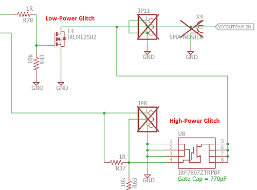
The "GLITCH" port is used for voltage glitching. It's connected to two MOSFET elements, as the following figure shows:
The CW1173 glitch output can be commanded to turn on either of those MOSFETs via scope.io.glitch_hp and scope.io.glitch_lp fields:
scope.io.glitch_hp = True #enable high power glitch
scope.io.glitch_hp = False #disable high power glitch

scope.io.glitch_lp = True #enable low power glitch
scope.io.glitch_lp = False #disable low power glitch
Be careful using this feature, as you don't want to short the MOSFETs for too long. It's also possible to damage the ChipWhisperer-Lite by burning these MOSFETs up if used incorrectly. See tutorial Fault_2 (https://chipwhisperer.readthedocs.io/en/latest/tutorials/fault_2-openadc-cwlitearm.html#tutorial-fault-2-openadc-cwlitearm) for more information.
Using Measure Port
The "MEASURE" port is the input to the low-noise amplifier and ADC.
== Using Measure Port == The "MEASURE" port is the input to the low-noise amplifier and ADC.
20-Pin Connector
The pinout is as follows:
| Number | Name | Dir | Description |
|---|---|---|---|
| 1 | +VUSB (5V) | O | Not Connected on ChipWhisperer-Lite. |
| 2 | GND | O | System GND. |
| 3 | +3.3V | O | +3.3V to Target Device, can be turned off, 200mA available. |
| 4 | FPGA-HS1 | I/O | High Speed Input (normally clock in). |
| 5 | PROG-RESET | I/O | Target RESET Pin (AVR Programmer). |
| 6 | FPGA-HS2 | I/O | High Speed Output (normally clock or glitch out). |
| 7 | PROG-MISO | I/O | SPI input: MISO (for SPI + AVR Programmer). |
| 8 | VTarget | I | Drive this pin with desired I/O voltage in range 1.5V-5V. |
| 9 | PROG-MOSI | I/O | SPI output: MOSI (for SPI + AVR Programmer). |
| 10 | FPGA-TARG1 | I/O | TargetIO Pin 1 - Usually UART TX or RX. |
| 11 | PROG-SCK | I/O | SPI output: SCK (for SPI + AVR Programmer). |
| 12 | FPGA-TARG2 | I/O | TargetIO Pin 2 - Usually UART RX or TX. |
| 13 | PROG-PDIC | I/O | PDI Programming Clock (XMEGA Programmer), or CS pin (SPI). |
| 14 | FPGA-TARG3 | I/O | TargetIO Pin 3 - Usually bidirectional IO for smartcard. |
| 15 | PROG-PDID | I/O | PDI Programming Data (XMEGA Programmer). |
| 16 | FPGA-TARG4 | I/O | TargetIO Pin 4 - Usually trigger input. |
| 17 | GND | O | |
| 18 | +3.3V | O | |
| 19 | GND | O | |
| 20 | +VUSB (5V) | O | Not Connected on ChipWhisperer-Lite. |
== 20-Pin Connector == The pinout is as follows:
| Number | Name | Dir | Description |
|---|---|---|---|
| 1 | +VUSB (5V) | O | Not Connected on ChipWhisperer-Lite. |
| 2 | GND | O | System GND. |
| 3 | +3.3V | O | +3.3V to Target Device, can be turned off, 200mA available. |
| 4 | FPGA-HS1 | I/O | High Speed Input (normally clock in). |
| 5 | PROG-RESET | I/O | Target RESET Pin (AVR Programmer). |
| 6 | FPGA-HS2 | I/O | High Speed Output (normally clock or glitch out). |
| 7 | PROG-MISO | I/O | SPI input: MISO (for SPI + AVR Programmer). |
| 8 | VTarget | I | Drive this pin with desired I/O voltage in range 1.5V-5V. |
| 9 | PROG-MOSI | I/O | SPI output: MOSI (for SPI + AVR Programmer). |
| 10 | FPGA-TARG1 | I/O | TargetIO Pin 1 - Usually UART TX or RX. |
| 11 | PROG-SCK | I/O | SPI output: SCK (for SPI + AVR Programmer). |
| 12 | FPGA-TARG2 | I/O | TargetIO Pin 2 - Usually UART RX or TX. |
| 13 | PROG-PDIC | I/O | PDI Programming Clock (XMEGA Programmer), or CS pin (SPI). |
| 14 | FPGA-TARG3 | I/O | TargetIO Pin 3 - Usually bidirectional IO for smartcard. |
| 15 | PROG-PDID | I/O | PDI Programming Data (XMEGA Programmer). |
| 16 | FPGA-TARG4 | I/O | TargetIO Pin 4 - Usually trigger input. |
| 17 | GND | O | |
| 18 | +3.3V | O | |
| 19 | GND | O | |
| 20 | +VUSB (5V) | O | Not Connected on ChipWhisperer-Lite. |
8-Pin SmartCard Connector
The CW1173 contains two 8-pin connectors, which use our standard 8-pin Smart-Card header pinout. One header connects to the SAM3U device (which has ISO-7816 drivers), one header connects to the FPGA. Note there is currently no firmware support for these devices, but the hardware is designed for any of the following:
- Emulating a smart card (use interposer board), or fuzzing a smart card reader
- Communicating to a smart card
- Sniffing traffic between a legitimate reader and smart card
- Side-channel analysis of smart card device
Header J7 (Connects to SAM3U):
| Number | Name | Dir | Description |
|---|---|---|---|
| 1 | VCCIO | O | 3.3V Supply (from linear regulator, always on) |
| 2 | GND | O | System GND |
| 3 | RST | I/O | Reset (SAM3U: PA3) |
| 4 | PRESENT | I | Used to detect presence of smart card (SAM3U: PA2) |
| 5 | CLK | I/O | Clock (SAM3U: PA25, 'CLK2'. FPGA: P131) |
| 6 | I/O | I/O | I/O Line (SAM3U: PA22), 10k pull-up |
| 7 | AUX1 | I/O | Spare line (SAM3U: PA4) |
| 8 | AUX2 | I/O | Spare line (SAM3U: PA5) |
Header J6 (Connects to FPGA):
| Number | Name | Dir | Description |
|---|---|---|---|
| 1 | VCCIO | O | 3.3V Supply (from FPGA supply) |
| 2 | GND | O | System GND |
| 3 | RST | I/O | Reset (FPGA: P102) |
| 4 | PRESENT/VPP | I | Not Connected (mount R60 to connect to P101) |
| 5 | CLK | I/O | Clock (FPGA: P100) |
| 6 | I/O | I/O | I/O Line (FPGA: P99), 10k pull-up |
| 7 | AUX1 | I/O | Spare line (FPGA: P98) |
| 8 | AUX2 | I/O | Spare line (FPGA: P97) |
Upgrading SAM3U Firmware
This section has been recently updated for ChipWhisperer 5. The previous version can be found here: https://wiki.newae.com/V4:CW1173_ChipWhisperer-Lite/Upgrading_SAM3U_Firmware
When talking about the ChipWhisperer's firmware, there is really two parts to this:
- The FPGA Bitstream file.
- The SAM3U USB interface chip firmware.
The FPGA bitstream alone is what is normally configured by the ChipWhisperer-Capture software. This bitstream is always the most up-to-date, since it's automatically reloaded by the computer every time you power cycle the ChipWhisperer-Capture. The SAM3U firmware however is not automatically updated, but it tends to change less frequently.
Checking Firmware Version
The firmware version is printed at start-up. You will see a line that looks like this indicating the version of the SAM3U Firmware:
Found CW-Lite, Serial Number = 442031204630xxxxxxxxxxx
SAM3U Firmware version = 0.11 b0
Programmed FPGA
If your firmware version is outdated, a warning will be printed. You can also see the firmware version in the Config CW Firmware dialog:
Note the main version is 0.11 in this example. The "b0" indicates a "build" number. Typically this will be "build 0", but special versions will use a different build number to indicate a variant of a regular version.
Upgrading Firmware
See https://chipwhisperer.readthedocs.io/en/latest/api.html#firmware-update for instructions on how to update the SAM3U firmware.
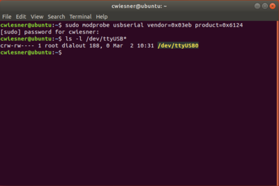
Linux usbserial module Workaround
There is an issue in some versions of Linux, where the SAM3U is not assigned a serial port when it enters bootloader mode. Here are some steps to resolve this issue (Note. this is not a permanent fix, you must go through these steps each time you put your ChipWhisperer into bootloader mode.). These steps assume you've already put ChipWhisperer into bootloader mode.
- Unplug your ChipWhisperer (Leave unplugged until instructed otherwise)
- Reboot your computer
- Once logged in again, open a terminal session
- Run this command:
sudo modprobe usbserial vendor=0x3eb product=0x6124 - Plug your ChipWhisperer back in
- Check that a serial port is now open using:
ls -l /dev/ttyUSB*
You should now be able to program the bootloader from ChipWhisperer Capture through the port you created
Manual Update
If the above instructions fail, there is no big problem. The SAM3U chip contains a hardware-resident bootloader. You may need to follow instructions on the Manual SAM3U Firmware Update page (including using BOSSA) if you are unable to use the automatic system that is part of ChipWhisperer-Capture.
Breaking Target Section Apart
You may wish to break the target section apart from the main capture board. This can easily be accomplished by following these instructions:
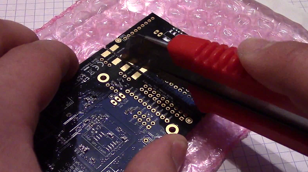
Using a sharp knife (such as Xacto knife or retractable safety knife), cut the traces on the bottom side of the board along the cut line. Pass the knife back and forth several times. Scoring the board deeply will make the breaking process easier and less stressful on the PCB:
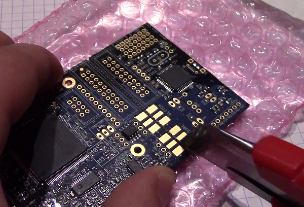
- Score the board on the top side:
- Select a surface to break the board over. It is suggested to have a piece of cardboard or boxboard down to protect components on the bottom side of the ChipWhisperer:
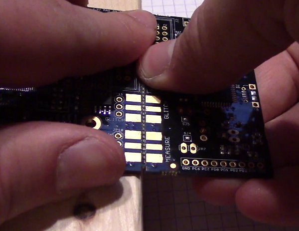
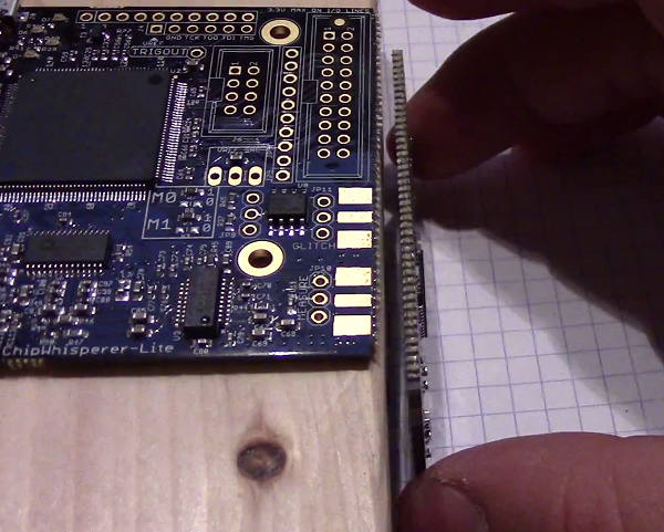
- Hold the main board section flat, apply even pressure to the target board section. It should snap downward:
- Separate the two sections:
You can see a Video of the process here:
Applying even pressure will help prevent damage to the ChipWhisperer-Lite main section. Flexing the PCB too much may cause damage to solder joints, but by holding the entire board flat against the edge this is prevented.
== Breaking Target Section Apart == You may wish to break the target section apart from the main capture board. This can easily be accomplished by following these instructions:
Using a sharp knife (such as Xacto knife or retractable safety knife), cut the traces on the bottom side of the board along the cut line. Pass the knife back and forth several times. Scoring the board deeply will make the breaking process easier and less stressful on the PCB:
- Score the board on the top side:
- Select a surface to break the board over. It is suggested to have a piece of cardboard or boxboard down to protect components on the bottom side of the ChipWhisperer:
- Hold the main board section flat, apply even pressure to the target board section. It should snap downward:
- Separate the two sections:
You can see a Video of the process here:
Applying even pressure will help prevent damage to the ChipWhisperer-Lite main section. Flexing the PCB too much may cause damage to solder joints, but by holding the entire board flat against the edge this is prevented.
Advanced Usage
Mounting Jumpers
Note the ChipWhisperer-Lite main board and target section contain a number of jumper options. By default these are not mounted, and solder jumper bridges on the PCB have been bridged to select the appropriate options when required. Some options are only solder jumpers, which to move the jumper requires a soldering iron to bridge or clear the appropriate connections.
The following lists jumpers on the ChipWhisperer-Lite / Target Section:
- Capture Section Jumpers
- JP4 is the "RESET" net for the SAM3U processor.
- JP2 causes the SAM3U processor flash memory to be erased. When the chip is erased a rom-resident bootloader takes over. See section XXXXX for bootloader details.
- JP5 selects the IO voltage for the FPGA bank which connects to the 20-pin target. By default SJ6 selects this to be 3.3V. It is not recommended to change this, as it is easy to damage the FPGA by feeding an out-of-range voltage in.
- SJ1 selects if the power supply comes from the Micro-USB connector (default) or an external 5V supply at the +5VIN pin.
- Target Section Jumpers
- JP7 connects the "MEASURE" SMA to the XMEGA VCC Rail. Shorted by default with SJ4.
- JP6 connects the "GLITCH" SMA to the XMEGA VCC Rail. Shorted by default with SJ5.
- JP12 can be used to feed an external voltage into the XMEGA VCC Rail. By default SJ3 connects this to 3.3V.
- SJ2 selects if the 3.3V rail comes from the 20-pin IDC connector (i.e. ChipWhisperer-Lite board), or via an optional LDO and USB connector.
