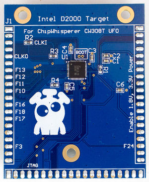
CW308T-D2000
| CW308T-D2000 | |
|---|---|
 | |
| Target Device | Intel Quark D2000 |
| Target Architecture | x86 |
| Hardware Crypto | No |
| Design Files | OSH Park PCBs |
The D2000 target is a bit of an oddball. It's an x86 target, but is really a microcontroller (internal flash etc).
Using Board
The CW308T-D2000 is used similar to any other CW308 Target Board. It does not accept an external oscillator, instead it outputs it's own oscillator for you to synchronize to. Specific caveats here:
- Be sure to mount J3 at lowest setting which routes the "CLKFB" line to "HS1/IN".
- You'll need to configure the ChipWhisperer to use an external clock input (EXTCLK or EXTCLK x4). This is taken care of by the D2000 setup script.
- The baud rate will need to be changed - it is scaled to be 115200 at 32 MHz. Use the frequency counter to measure the actual frequency & scale baud rate appropriately. Depending on the ROM loaded the clock varies. This is taken care of by the D2000 setup script.
- The TX/RX are opposite compared to the XMEGA. This is taken care of by the D2000 setup script.
The following shows an example setup script for this board:
scope.gain.gain = 45
scope.adc.samples = 25000
scope.adc.offset = 0
scope.adc.basic_mode = "rising_edge"
scope.clock.clkgen_freq = 7370000
scope.clock.adc_src = "extclk_x4"
scope.trigger.triggers = "tio4"
#TX/RX backwards from XMEGA
scope.io.tio1 = "serial_tx"
scope.io.tio2 = "serial_rx"
scope.io.hs2 = None

# Sample delay - you may need to increase this!
# Gives time for frequency measurement to occur in hardware.
time.sleep(0.5)

ext_freq = scope.clock.freq_ctr

if ext_freq > 10:

    baud = (115200 / 32E6) * ext_freq
    print "Based on extclk of %d Hz, setting baud to %d" % (ext_freq, baud)
    target.baud = baud

else:
    raise IOError("Did not detect external clock from D2000. Confirm jumpers and rerun, or increase delay before sample."
Building Firmware
To build firmware for the D2000, you'll need to download the Intel ISSM Toolchain and uncompress it. The toolchain comes compressed/archived in the tar.gz format, so you may need to download a program that can work with those formats (such as 7-zip on Windows). Firmware is contained in hardware/victims/firmware/intel_quark/simpleserial_example/ and can be built with make. Note that you'll need to specify where the toolchain is located:
Specifying Toolchain Location
If you're using cmd on Windows (as opposed to something like Git Bash or Cygwin, you'll need to create a new environment variable called IAMCU_TOOLCHAIN_DIR and set its value to the path to the toolchain. For example, I uncompressed the toolchain to C:\Users\User\Downloads and set the variable to C:\Users\User\Downloads\issm-toolchain-windows-2017-01-25\tools\compiler\gcc-ia\5.2.1\bin. Otherwise, running export /path/to/toolchain/bin should work on Mac, Linux, Git Bash, Cygwin, etc.
Troubleshooting
- No such file or directory when building on Windows
- This is usually caused by the default make directory command (
md) not working. First, ensure that you havemkdirand cp on your system by openingcmdand running them. Then openhardware/victims/firmware/intel_quark/qmsi/base.mkand change:to:# Any other version of Windows mkdir = @md $(subst /,\,$(1)) > nul 2>&1 || exit 0 copy = @copy $(subst /,\,$(1)) $(subst /,\,$(2)) > nul 2>&1 || exit 0
# Any other version of Windows
mkdir = @mkdir -p $(1) || exit 0
copy = @cp $(1) $(2) || exit 0
- This is usually caused by the default make directory command (
Programming
An external programmer is needed for this target. The Quark D2000 dev-board can be used with jumper wires, or a standard OpenOCD programmer can be used. The suggested programmer is the Olimex ARM-USB-OCD-H as is available from suppliers such as Mouser and Digi-Key (mouser link provided).
The D2000 chips have a weird combination of what they call "ROM" (actually not ROM remotely) and application space. When building you normally use the D2000 ROM provided (or can build your own). However you only need to program this section the first time - it is not recommended to reprogram it unless needed, since it is possible to brick the D2000 with a corrupt ROM load.
The D2000 boards come loaded with an example ROM & application as well already.
OpenOCD Board Setup
If using OpenOCD either stand-alone or as part of Intel ISSM, you'll need to define a new board file. The file is based on scripts\board\quark_d2000.cfg found in the following directory: C:\IntelSWTools\ISSM_2016.0.027\tools\debugger\openocd\scripts\board (adjust for version number changes).
You will find a line like the following in the original file:
 #default frequency but this can be adjusted at runtime
 adapter_khz 1000
Make a copy of the file, but change that to a slower speed (suggested is 125 kHz)
 #default frequency but this can be adjusted at runtime
 adapter_khz 125
Save this file as quark_d2000_ufo.cfg.
How to flash D2000 board using OpenOCD
We'll modify the provided scripts from the Intel ISSM distribution (compiler etc for D2000). Start a Windows command prompt and run the following commands. You may have to change the directory of the first command to match your version of Intel ISSM (eg. C:\IntelSWTools\ISSM_2016.0.027\issm_env.bat):
C:\IntelSWTools\ISSM_2016.2.097\issm_env.bat
cd %ISSM_DEBUGGER_ROOT%\openocd
bin\openocd.exe -f scripts\interface\ftdi\olimex-arm-usb-ocd-h.cfg -f scripts\board\quark_d2000_ufo.cfg
Note we specify two script files - the first had the JTAG connection (the olimex-arm-usb-ocd-h.cfg), the second had the D2000. This should result in an output like the following:
Open On-Chip Debugger 0.8.0-dev-g7845893 (2015-11-26-18:12)
Licensed under GNU GPL v2
For bug reports, read
       http://openocd.sourceforge.net/doc/doxygen/bugs.html
Info : only one transport option; autoselect 'jtag'
adapter speed: 125 kHz
trst_only separate trst_push_pull
flash_rom
Info : clock speed 125 kHz
Info : JTAG tap: quark_d2000.cltap tap/device found: 0x0e786013 (mfg: 0x009, part: 0xe786, ver: 0x0)
Enabling lmt core tap
Info : JTAG tap: quark_d2000.lmt enabled
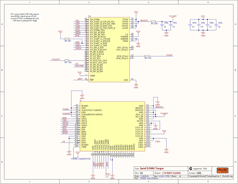
If you get errors here, confirm the JTAG clock speed is not running too quickly. You need to modify the example script file to slow down the JTAG speed for this board (due to shunt resistor inline with VCC-core).
At this point it will hold, waiting for new commands. There is two ways to proceed:
Connecting with GDB
Connecting and programming with GDB may be preferred if you wish to also do any debug. It however is more limited in what commands you can run. If this does not work see the next section about using telnet commands. Open a second command prompt, and run:
C:\IntelSWTools\ISSM_2016.0.027\issm_env.bat
gdb
You can then run the following within a GDB console:
target remote :3333
monitor clk32M 125
monitor load_image C:\\chipwhisperer\\hardware\\victims\\firmware\\intel_quark\\quark_d2000_rom.bin 0x0
monitor load_image C:\\chipwhisperer\\hardware\\victims\\firmware\\intel_quark\\simpleserial_example\\release\\quark_d2000\\x86\\bin\\simpleserial_aes.bin 0x00180000
The first load_image is used for the ROM image. This should only be done once - do not reload every time, only reload the application. The boards as shipped come with a ROM image so you can skip that step if using the NewAE example code.
Notes:
- The
monitor clk32M 125sets a 125 kHz JTAG clock frequency. This may be too slow, but is recommended especially when loading ROM due to potential for misprogramming on the target board due to the shunt resistor. Note it takes a long time (~60 seconds) to program the ROM code so don't abort it! - If the above fails, see the next note on recovering normal settings with the telnet interface.
- You can short F13 (GPIO1 on the ChipWhisperer-Lite) to GND to force the JTAG pins on. It is suggested to do this via the ChipWhisperer-Lite software (setting it as a GPIO output and then setting it low). This requires the 'ROM' code programmed in already.
- Do not reload the ROM code unless needed -- this is the boot code and if something gets corrupt it can brick the device.
Connecting with Telnet to Monitor
When running the target remote :3333 or other commands above, you may encounter errors that seem fatal. Do not fret, you can likely recover everything using another mode. To do so:
- Power cycle the target board, and re-run the openocd command previously specified (assuming you have encountered errors and the system is in an unknown state).
- If this fails, set GPIO1 to LOW, and power cycle the target. Try connecting again.
Assuming the connect works, open a second command prompt and run
telnet localhost 4444
Note the port connected to is 4444 (not :3333) as before. This now enters the monitor directly, and you can try running the following commands:
reset halt
set QUARK_D2000_OTPC_DATA_WRITE_ENABLED 1
mass_erase
clk32M 100
load_image C:\\chipwhisperer\\hardware\\victims\\firmware\\intel_quark\\quark_d2000_rom.bin 0x0
load_image C:\\chipwhisperer\\hardware\\victims\\firmware\\intel_quark\\simpleserial_example\\release\\quark_d2000\\x86\\bin\\simpleserial_aes.bin 0x00180000
The following should be the example output of these commands:
> reset halt
JTAG tap: quark_d2000.cltap tap/device found: 0x0e786013 (mfg: 0x009, part: 0xe786, ver: 0x0)
Enabling lmt core tap
JTAG tap: quark_d2000.lmt enabled
target state: halted
target halted due to debug-request at 0x0000ffff in real mode
target state: halted
target halted due to debug-request at 0x0000fff0 in real mode
> set QUARK_D2000_OTPC_DATA_WRITE_ENABLED 1
1
> mass_erase
Deleting  OTPC, OTPD and FLASH regions
0xb0100014: 00000001
> clk32M 100
adapter speed: 3 kHz
adapter speed: 100 kHz
JTAG tap: quark_d2000.cltap tap/device found: 0x0e786013 (mfg: 0x009, part: 0xe786, ver: 0x0)
Enabling lmt core tap
JTAG tap: quark_d2000.lmt enabled
target state: halted
target halted due to debug-request at 0x0000fff0 in real mode
> load_image C:\\chipwhisperer\\hardware\\victims\\firmware\\intel_quark\\quark_d2000_rom.bin 0x0
....8192 bytes written at address 0x00000000
downloaded 8192 bytes in 66.997505s (0.119 KiB/s)
> load_image C:\\chipwhisperer\\hardware\\victims\\firmware\\intel_quark\\simpleserial_example\\release\\quark_d2000\\x8
.2872 bytes written at address 0x00180000
downloaded 2872 bytes in 42.280869s (0.066 KiB/s)
Note you can try the following if still having trouble:
- Use a slower JTAG clock speed. Be SURE you are using a custom .cfg file which specifies the slower JTAG speed on initial connect (and not just as part of the clk32M commands).
- Short the SHUNTH/SHUNTL pins.
Schematic
See GIT Repo for PDF of schematic. Note there is a new "03C" rev that changes the shunt resistor (R1) to a 1-ohm resistor. This results in a much more reliable device, as the original 10-ohm shunt caused occasional crashes. If you are using an older revision device, you can mount a shunt/jumper between "SH-" and "SH+" on the UFO board to achieve a similar effect.
Board Layout
See GIT Repo for gerber files.
