SASEBO-W Target
The SASEBO-W is no longer supported, as the OpenADC build had considerable reliability issues. You can instead use a separate ChipWhisperer capture hardware with the SASEBO-W.
Using the SASEBO-W With the OpenADC
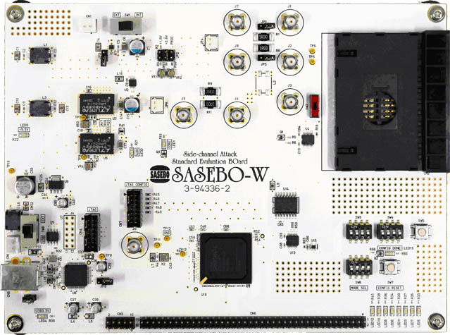
Preparing the SASEBO-W Hardware
The SASEBO-W must be prepared for use with the ChipWhisperer system. This requires a few steps:
Program the correct files into the main FPGA. The ChipWhisperer releases are built for The Spartan 6 LX150 device, if you have a different FPGA on the SASEBO-W you will have to rebuild the Xilinx ISE project.
You can program just the bitstream located at
hardware\capture\sasebow-integrated\hdl\sasebow-chipwhisperer.bit. This DOES NOT modify anything permantly if you don't want to modify the SPI flash.You can program the MCS file at
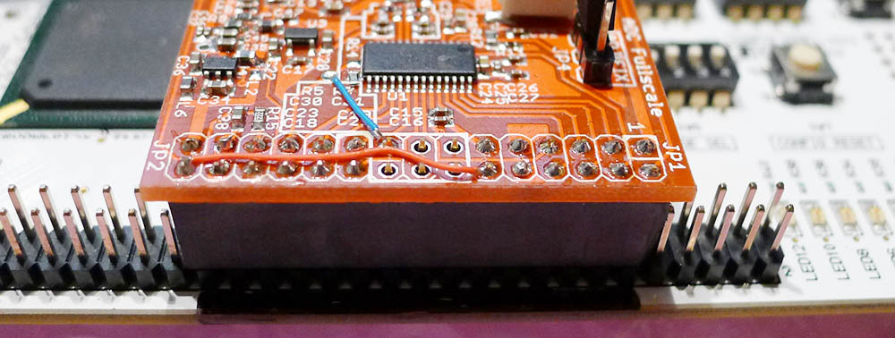
sasebow-chipwhisperer-unpadded.mcsinto the FLASH chip on the SASEBO-W. This makes the system always power on as a ChipWhisperer-attached device.Assuming you have the OpenADC set up correctly, simply mount on the header pins. Be SURE to mount at the correct location, as putting power on the wrong pins may DESTROY the OpenADC.
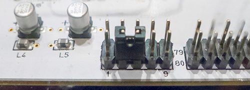
Mount a header on CN3, which shorts two of the GND planes together. This step is REQUIRED FOR A RELIABLE CONNECTION, you can see a blog post on Split GND Plane for details. The connection is between pins 3 and 5:
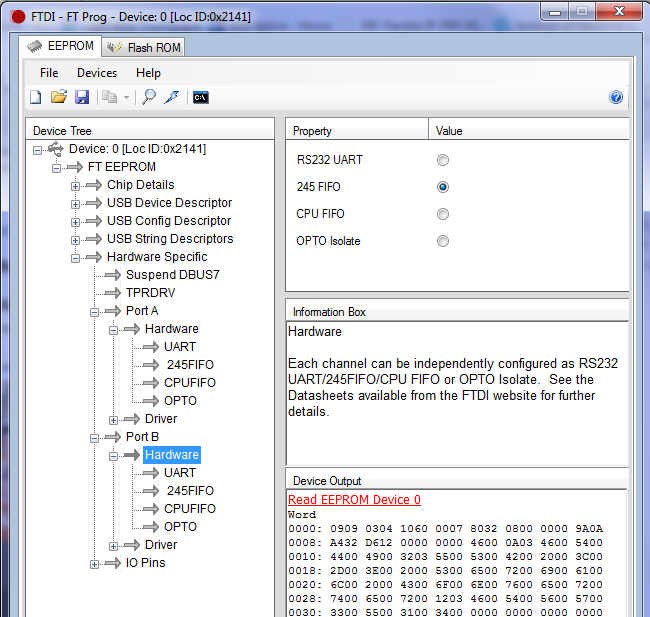
Using FT Prog, setup the FT2232H device on both Channel A & B for 'FT 245 FIFO' mode. You MUST program the EEPROM to set both Channels A & Channel B for FT 245 FIFO mode. The following image shows this being done:
Running the SASEBO-W Example
The SASEBO-W example assumes you are using the SASEBO-W CardOS, and attacking the AES implementation. In this case:
- Ensure you've setup the hardware as above
- Insert a card into the smartcard reader
- Run the ChipWhisperer-Capture program
Run the SASEBO-W example:
See the Tutorial_B10_Using_with_SASEBO-W_CardOS_or_DPA_Contest_v4.2 for details, including using different target boards.
More Information
Additional information is currently posted on the ChipWhisperer Wiki at these pages:
- https://www.assembla.com/spaces/chipwhisperer/wiki/SASEBO-W
- https://www.assembla.com/wiki/show/chipwhisperer/SASEBO-W_Programming_Information
In addition see the following tutorial as part of this documentation:
- Tutorial_B10_Using_with_SASEBO-W_CardOS_or_DPA_Contest_v4.2
Connecting the Multi-Target Board to the SASEBO-W
warningIt is completely possible to use the EXT. IO voltage, allowing the ChipWhisperer to interface with 5V SmartCards. Before doing this follow all warnings in section CW301_Multi-Target#Target_Voltage_Selection, or you may DESTROY THE CHIPWHISPERER DEVICE by shunting the external power supply onto internal 3.3V rails.
It is possible to use the AVR microcontroller on the Multi-Target board to connect to the SASEBO-W. This requires the use of the SASEBO-W adapter, a small PCB with the pinout of the connector used on the SASEBO-W board.
This is advantageous as it allows the continued use of AVR-based code without needing to find old AVR type SmartCards. Instead the modern AtMega328P (or similar) is programmed, which can typically be made to run existing AVR code targetting the Mega163 or similar (i.e. the FunCard type device).
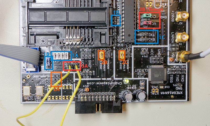
First, some jumper settings are required, as shown in this image:
Settings are:
- 1.
- Mount all four jumpers on 'AVR-PROG' section (JP8). This bridges the Smart-Card IO Connections to the AVR Microcontroller.
- Set JP23, Labled I/O to 'DUP'.
- Remove jumpers JP5 and JP6 from the AVR section (this isn't strictly required, as the serial lines could also be used)
- Remove jumper JP28, the AVR-TRIG jumper. Early version of the multi-target board do not have this jumper, and it's removal is not strictly required.
- 2.
- Remove all jumpers from JP18, which frees up the 'CLKOSC' net on the PCB.
- Set the CLKOSC jumper in the smartcard section, which bridges the external clock to the CLKOSC net.
- Set the CLKOSC jumper in the AVR section, which bridges the CLKOSC net to the AVR Clock Input.
- 3.
Using a jumper wire, bridge the external VCC power supply from the smartcard socket to the 3.3V rail of the multi-target board.
warning
Performing step 3A requires that your external power supply is 3.3V or lower. Do not use when the SmartCard is powered by 5V. The SASEBO-W by default uses a 3.0V supply for the SmartCard, allowing this configuration.
warning
Do not connect the ChipWhisperer Capture Rev2 to the 20-pin connector on the Multi-Target board in this configuration. This would result in two conflicting power supplies being pushed onto the 3.3V rail.
- When programming the AVR using the SASEBO-W, you will have to set the 'VCC' and 'GND' jumpers (JP1) as in the photo, which removes the resistive shunts from the power supplies. When performing side-channel attacks, you should set them back to the normal configuration, which allows the power measurement across the resistor.
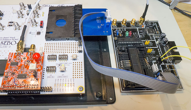
Finally, you can then use the SASEBO-W adapter to connect the Multi-Target board to the SASEBO-W. The power measurement should be taken from the shunt on the Multi-Target board, as this will be considerably lower noise.
Porting Code to AtMega328P
Connections to the AtMega328P are shown in the following table:
| SmartCard | ATMega328P | Mega163 Card |
|---|---|---|
| Clock | XTAL1 | XTAL1 |
| Reset | /Reset | /Reset |
| I/O | PORTB.4 (MISO) | PORTB.6 (MISO) + PORTD.7 |
| AUX1 | PORTB.3 (MOSI) | PORTB.5 (MOSI) |
| AUX2 | PORTB.5 (SCK) | PORTB.7 (SCK) |
Note this means code written for the Mega163 card will require minor changes to run on the AtMega328P.
Programming Mega328P Via SASEBO-W
The quick-start guide for the SASEBO-W includes details of using the 'avrdude' program to program the MegaCard. This will also work for the AtMega328P, it simply requires you to change the device on the command line to 'mega328p'.
There appears to be an error in the programming system that requires you to remove and reinsert the SASEBO-W adapter card before the programming will succeed. Once it has occurred once, you must again power remove/reinsert the adapter, or remove/reinsert the 8-pin connector.
