| As of August 2020 the site you are on (wiki.newae.com) is deprecated, and content is now at rtfm.newae.com. |
CW1173 ChipWhisperer-Lite
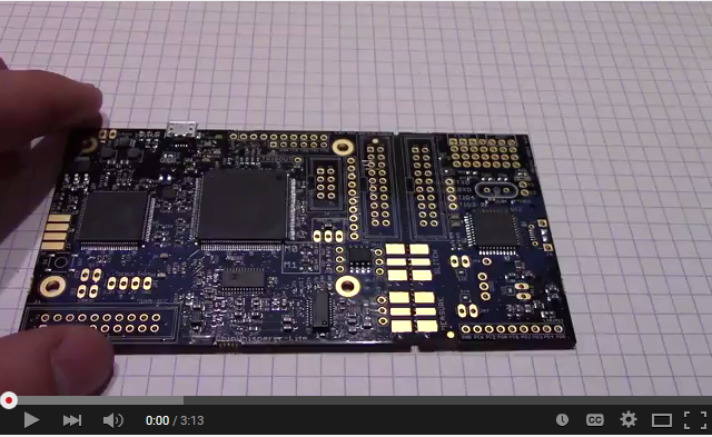
The ChipWhisperer-Lite Bare Board consists of two main parts: a multi-purpose power analysis capture instrument, and a target board. The target board is a standard microcontroller which you can implement algorithms onto. For example if you wish to evaluate an AES library, you can program that library into the target board and perform the power analysis.

Contents
Quick-Start Guide
Basic Usage Instructions
CW-Lite: Programming AVR/XMEGA Device
The CW1173 has built-in support for programming either Atmel AVR or Atmel XMEGA device. This is designed to allow you to program our target boards (either the built-in XMEGA target, or the Multi-Target board).
Note this programmer is fairly simple, and does not provide all the features of a stand-alone programmer.
AVR Programmer
The AVR device programmer requires four connections to the target: RESET, MOSI, MISO, SCK. See #20-Pin_Connector for details of AVR programming pin connections.
Accessing the Programming
To access the AVR Programmer, select the "CW-Lite AVR Programmer" from the pull-down Tools menu:

Which should give you the AVR Programmer Window.
Clock Source Selection
Note to use the AVR programmer you may require a valid clock source for the AVR. It is suggested to select one of the setup scripts (such as ChipWhisperer-Lite: AES Simple-Serial on ATMega328P) which will generate a 7.37 MHz clock.
Check if the device is found by pressing the "Check Signature" button. The status window will show the detected device based on the signature.

If this fails, double-check connections, and ensure the clock source to the AVR is suitable. Note some errors will appear as part of the main window log:

The default SPI data rate for the programmer is too fast for devices which are running slower than 2 MHz. If programming a device with a clock source slower than 2 MHz, you will need to enable the "Slow Clock Mode". In "Slow Clock Mode" the entire SAM3U and FPGA clock is changed from 96 MHz to 12 MHz. Note the default fuse bytes for a virgin ATMega328P result in a 1 MHz clock, so you will need to use "slow clock mode" to program the correct fuse bytes, after which point you will not need to use "slow clock mode".
noteThe 'slow clock mode' is used to provide a slower SPI clock than would otherwise be possible. When switching into 'slow clock mode' it will cause all DCM blocks in the FPGA to become unlocked. You will need to reset the DCM blocks, or simply restart the CW-Capture software and run the setup script.
Programming the Fuses
By default the AVR programmer allows you to modify the LOW fuse byte only, as this byte controls the clock source selection. To change the value of the fuse byte:
- Press the "Read Fuses" button, and the values should be populated
- Specify the new low fuse value
- Hit "Write Fuses"
See an Online Fuse Calculator to better understand what the values mean.
tip
- If programming a virgin ATMega328P device, the default low-fuse value of
62results in the internal- 8 MHz oscillator being divided down to 1 MHz. Any external clock is ignored.
The low fuse byte must be changed to
D0to use the external clock provided by the ChipWhisperer toolchain.
Programming the Flash
Programming the flash is accomplished by selecting the new .hex file in the "Find" menu, and pressing the "Erase/Program/Verify FLASH" button. The "Status" line will show the following information:
- File programmed into device
- Time file was last modified (very useful to confirm you are using changed file when doing development)
- Status of verification, and number of bytes programmed/verified

XMEGA Programmer
The XMEGA device programmer requires only two connections to the target: clock (PDIC) and data (PDID). The PDIC line is usually shared with the RESET pin, and the PDID pin is a specific pin on the XMEGA device. See #20-Pin_Connector for details of XMEGA programming pin connections.

Using Glitch Port
The "GLITCH" port is used for voltage glitching. It's connected to two MOSFET elements, as the following figure shows:

The CW1173 glitch output can be commanded to turn on either of those MOSFETs via the "Glitch Out Enable" checkboxes:

Be careful using this feature, as you don't want to short the MOSFETs for too long. It's also possible to damage the ChipWhisperer-Lite by burning these MOSFETs up if used incorrectly. See tutorial #A3 for more information on using this feature.
Using Measure Port
The "MEASURE" port is the input to the low-noise amplifier and ADC.
20-Pin Connector
The pinout is as follows:
| Number | Name | Dir | Description |
|---|---|---|---|
| 1 | +VUSB (5V) | O | Not Connected on ChipWhisperer-Lite. |
| 2 | GND | O | System GND. |
| 3 | +3.3V | O | +3.3V to Target Device, can be turned off, 200mA available. |
| 4 | FPGA-HS1 | I/O | High Speed Input (normally clock in). |
| 5 | PROG-RESET | I/O | Target RESET Pin (AVR Programmer). |
| 6 | FPGA-HS2 | I/O | High Speed Output (normally clock or glitch out). |
| 7 | PROG-MISO | I/O | SPI input: MISO (for SPI + AVR Programmer). |
| 8 | VTarget | I | Drive this pin with desired I/O voltage in range 1.5V-5V. |
| 9 | PROG-MOSI | I/O | SPI output: MOSI (for SPI + AVR Programmer). |
| 10 | FPGA-TARG1 | I/O | TargetIO Pin 1 - Usually UART TX or RX. |
| 11 | PROG-SCK | I/O | SPI output: SCK (for SPI + AVR Programmer). |
| 12 | FPGA-TARG2 | I/O | TargetIO Pin 2 - Usually UART RX or TX. |
| 13 | PROG-PDIC | I/O | PDI Programming Clock (XMEGA Programmer), or CS pin (SPI). |
| 14 | FPGA-TARG3 | I/O | TargetIO Pin 3 - Usually bidirectional IO for smartcard. |
| 15 | PROG-PDID | I/O | PDI Programming Data (XMEGA Programmer). |
| 16 | FPGA-TARG4 | I/O | TargetIO Pin 4 - Usually trigger input. |
| 17 | GND | O | |
| 18 | +3.3V | O | |
| 19 | GND | O | |
| 20 | +VUSB (5V) | O | Not Connected on ChipWhisperer-Lite. |
8-Pin SmartCard Connector
The CW1173 contains two 8-pin connectors, which use our standard 8-pin Smart-Card header pinout. One header connects to the SAM3U device (which has ISO-7816 drivers), one header connects to the FPGA. Note there is currently no firmware support for these devices, but the hardware is designed for any of the following:
- Emulating a smart card (use interposer board), or fuzzing a smart card reader
- Communicating to a smart card
- Sniffing traffic between a legitimate reader and smart card
- Side-channel analysis of smart card device
Header J7 (Connects to SAM3U):
| Number | Name | Dir | Description |
|---|---|---|---|
| 1 | VCCIO | O | 3.3V Supply (from linear regulator, always on) |
| 2 | GND | O | System GND |
| 3 | RST | I/O | Reset (SAM3U: PA3) |
| 4 | PRESENT | I | Used to detect presence of smart card (SAM3U: PA2) |
| 5 | CLK | I/O | Clock (SAM3U: PA25, 'CLK2'. FPGA: P131) |
| 6 | I/O | I/O | I/O Line (SAM3U: PA22), 10k pull-up |
| 7 | AUX1 | I/O | Spare line (SAM3U: PA4) |
| 8 | AUX2 | I/O | Spare line (SAM3U: PA5) |
Header J6 (Connects to FPGA):
| Number | Name | Dir | Description |
|---|---|---|---|
| 1 | VCCIO | O | 3.3V Supply (from FPGA supply) |
| 2 | GND | O | System GND |
| 3 | RST | I/O | Reset (FPGA: P102) |
| 4 | PRESENT/VPP | I | Not Connected (mount R60 to connect to P101) |
| 5 | CLK | I/O | Clock (FPGA: P100) |
| 6 | I/O | I/O | I/O Line (FPGA: P99), 10k pull-up |
| 7 | AUX1 | I/O | Spare line (FPGA: P98) |
| 8 | AUX2 | I/O | Spare line (FPGA: P97) |
Upgrading SAM3U Firmware
When talking about the ChipWhisperer-Lite's firmware, there is really two parts to this:
- The FPGA Bitstream file.
- The SAM3U USB interface chip firmware.
The FPGA bitstream alone is what is normally configured by the ChipWhisperer-Capture software. This bitstream is always the most up-to-date, since it's automatically reloaded by the computer every time you power cycle the ChipWhisperer-Capture. The SAM3U firmware however is not automatically updated, but it tends to change less frequently.
Checking Firmware Version
The firmware version is printed at start-up. You will see a line that looks like this indicating the version of the SAM3U Firmware:
Found CW-Lite, Serial Number = 442031204630xxxxxxxxxxx
SAM3U Firmware version = 0.11 b0
Programmed FPGA
If your firmware version is outdated, a warning will be printed. You can also see the firmware version in the Config CW Firmware dialog:

Note the main version is 0.11 in this example. The "b0" indicates a "build" number. Typically this will be "build 0", but special versions will use a different build number to indicate a variant of a regular version.
Upgrading Firmware
Before updating, you must put your ChipWhisperer-Lite into bootloader mode. Once put into this mode you will need to load a new firmware file. There is two ways of doing it: the automatic method, and the manual method. The automatic method is done through the GUI, and works if you have valid firmware image loaded. The manual method is always guaranteed to work.
The automatic method is:
Using ChipWhisperer-Capture GUI
- Connect to the ChipWhisperer-Lite.
- From the Tools menu select Config CW Firmware
- Select the Open SAM3U Update Widget button.
- Press the Enable Bootloader Mode button.
- You will get an error, and the ChipWhisperer-Lite will disconnect. This is normal, and indicates the USB mode changed suddenly.
- The blue LED will stop flashing, and the device will reconnect in programmer mode (see below).
Once you are in bootloader mode, both the blue and red LED will be very dimmly lit:

This indicates it is in bootloader mode. The device will now attach as a serial port. If you are using Windows this may take a few minutes to happen.
If using Linux, you can use dmesg to verify the serial port was connected OK.
If this doesn't work, see the page Manual SAM3U Firmware Update for details on how to manually enter bootloader mode. You can return to this page for the actual programming - you don't need to install/use the BOSSA utility if you follow those manual directions. You simply need to force the system into bootloader mode using those directions.
To actually program the file, we use the second part of the dialog box you already had open:

Once we are in bootloader mode, you can follow these steps:
- Hit "Update List", and select the serial port the SAM3U attached as.
- To use the default firmware file, leave the "Built-in" radio-box selected. If you want a custom firmware you can select the "External" mode.
- Hit the "Run Program" button
- Once completed, unplug/replug your device and it should come to life.
- Close the update widgets, and reconnect to your ChipWhisperer-Lite.
Manual Update
If the above instructions fail, there is no big problem. The SAM3U chip contains a hardware-resident bootloader. You may need to follow instructions on the Manual SAM3U Firmware Update page (including using BOSSA) if you are unable to use the automatic system that is part of ChipWhisperer-Capture.
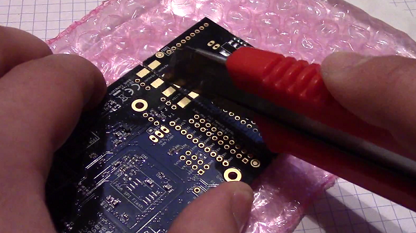
Breaking Target Section Apart
You may wish to break the target section apart from the main capture board. This can easily be accomplished by following these instructions:
Using a sharp knife (such as Xacto knife or retractable safety knife), cut the traces on the bottom side of the board along the cut line. Pass the knife back and forth several times. Scoring the board deeply will make the breaking process easier and less stressful on the PCB:
- Score the board on the top side:


- Select a surface to break the board over. It is suggested to have a piece of cardboard or boxboard down to protect components on the bottom side of the ChipWhisperer:

- Hold the main board section flat, apply even pressure to the target board section. It should snap downward:

- Separate the two sections:

You can see a Video of the process here:
Applying even pressure will help prevent damage to the ChipWhisperer-Lite main section. Flexing the PCB too much may cause damage to solder joints, but by holding the entire board flat against the edge this is prevented.
Advanced Usage
Mounting Jumpers
Note the ChipWhisperer-Lite main board and target section contain a number of jumper options. By default these are not mounted, and solder jumper bridges on the PCB have been bridged to select the appropriate options when required. Some options are only solder jumpers, which to move the jumper requires a soldering iron to bridge or clear the appropriate connections.
The following lists jumpers on the ChipWhisperer-Lite / Target Section:
- Capture Section Jumpers
- JP4 is the "RESET" net for the SAM3U processor.
- JP2 causes the SAM3U processor flash memory to be erased. When the chip is erased a rom-resident bootloader takes over. See section XXXXX for bootloader details.
- JP5 selects the IO voltage for the FPGA bank which connects to the 20-pin target. By default SJ6 selects this to be 3.3V. It is not recommended to change this, as it is easy to damage the FPGA by feeding an out-of-range voltage in.
- SJ1 selects if the power supply comes from the Micro-USB connector (default) or an external 5V supply at the +5VIN pin.
- Target Section Jumpers
- JP7 connects the "MEASURE" SMA to the XMEGA VCC Rail. Shorted by default with SJ4.
- JP6 connects the "GLITCH" SMA to the XMEGA VCC Rail. Shorted by default with SJ5.
- JP12 can be used to feed an external voltage into the XMEGA VCC Rail. By default SJ3 connects this to 3.3V.
- SJ2 selects if the 3.3V rail comes from the 20-pin IDC connector (i.e. ChipWhisperer-Lite board), or via an optional LDO and USB connector.
</span>